background image

Power PMAC Clipper User Manual 

Connections and Software Setup


46 


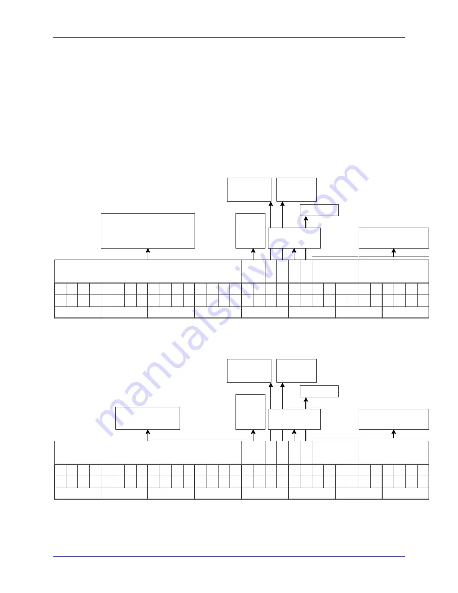
Bit #13 specifies the trigger mode. Typically set to 0 for continuous (on-going position). 


Bit #12 is the trigger enable bit, must be set to 1 to trigger. 


Bit #11 specifies whether a Gray to Binary conversion is necessary. 


Bit #10 is a read-only bit. 


Bits [9 – 6] are status bits. 


Bits [5 – 0] specify the encoder protocol resolution (in bits). 


SSI 

Bit #:

Binary:

0

Bit Length 

(Resolution)

Hex ($):

1

2

3

0

0

0

0

4

5

6

7

0

0

0

0

8

9

10

11

0

0

0

0

12

13

14

15

0

0

0

0

16

17

18

19

0

0

0

0

20

21

22

23

0

0

0

0

24

25

26

27

0

0

0

0

28

29

30

31

0

0

0

0

0

0

0

0

0

0

0

0

Status

Bits

D

at

aR

d

y

G

 t

o

 B

Tr

ig

 E

n

a

M

o

d

e

Parity

Command

Encoder Dependent

0 for SSI

00: None
01: Odd
10: Even

0: Continuous
1: One Shot

0: Disable
1: Enable

0: No Conversion
1: Gray to Binary

Read Only

Single Turn + Multi 

Turn


EnDat 

In this example, a 37-bit (25-bit Single-Turn, 12-bit Multi-Turn) EnDat 2.2 encoder configuration. 
 

Bit #:

Binary:

0

Bit Length 

(Resolution)

Hex ($):

1

2

3

1

0

1

0

4

5

6

7

0

1

0

0

8

9

10

11

0

0

0

0

12

13

14

15

1

0

0

0

16

17

18

19

1

1

1

0

20

21

22

23

0

0

0

0

24

25

26

27

0

0

0

0

28

29

30

31

0

0

0

0

5

2

0

1

7

0

0

0

Status

Bits

D

at

aR

d

y

G

 t

o

 B

Tr

ig

 E

n

a

M

o

d

e

Parity

Command

$7: Report position

$2A: Reset Encoder

00: None
01: Odd
10: Even

0: Continuous
1: One Shot

0: Disable
1: Enable

0: No Conversion
1: Gray to Binary

Read Only

Single Turn + Multi 

Turn


Serial Data Registers 

The resulting serial encoder – position – data is found in the serial data registers A, and B. 

Содержание Power PMAC Clipper

Страница 1: ...lity Ease of Use 21314 Lassen St Chatsworth CA 91311 Tel 818 998 2095 Fax 818 998 7807 www deltatau com 1 User Manual 3Power PMAC Clipper 4 4 4050xx0 xx0 xxx0xx April 15 2016 DELTA TAU Data Systems In...

Страница 2: ...ssories and amplifiers contain static sensitive components that can be damaged by incorrect handling When installing or handling Delta Tau Data Systems Inc products avoid contact with highly insulated...

Страница 3: ...e to static electricity and can be damaged by incorrect handling Avoid contact with high insulating materials artificial fabrics plastic film etc Place the product on a conductive surface Discharge an...

Страница 4: ...Power PMAC Clipper User Manual REVISION HISTORY REV DESCRIPTION DATE CHG APPVD 0 Preliminary 10 13 14 Sgm 1 Released 07 21 15 RN RN 2 Update motor setup 04 15 16 Sgm Sgm...

Страница 5: ......

Страница 6: ...AND SOFTWARE SETUP 21 Default Jumper Configurations 21 TB1 JPWR Power Supply Input 21 J2 Serial Port 23 J3 Machine Connector JMACH1 Port 24 Configuring Quadrature Encoders 27 Wiring the DAC Output 29...

Страница 7: ...p Test Encoder Decode 62 Position Loop PID Gains 63 Typical Settings for Four Channels of Filtered PWM Setup 64 Pulse Frequency Modulation Output Step and Direction 66 Multi Channel Setup Elements 66...

Страница 8: ...tiplexed I O on the JTHW port 80 J9 General Purpose Digital Inputs and Outputs JOPT Port 81 General Purpose I O J6 Structures 81 J10 Handwheel and Pulse Dir Connector JHW PD Port 82 Handwheel Encoder...

Страница 9: ...s in a Power Clipper application can be expanded to 8 with the optional ACC 24S3 The Power Clipper comes with 32 general purpose digital I O points which can be expanded through the optional ACC 34AA...

Страница 10: ...is manual is enclosed in the following format Power PMAC script format example GLOBAL MyCounter 0 Arbitrary global variable counter GLOBAL MyCycles 10 Arbitrary global variable number of cycles User I...

Страница 11: ...standard configuration of the Power Clipper provides the following features CPU 1 0 GHz Dual Core Power PC 465EX CPU Memory 1 GB DDRAM3 active memory 1 GB NAND Flash non volatile memory Communication...

Страница 12: ...on selectable by byte flat cable connection to Delta Tau ACC 34x boards Stacking Connector Configuration The standard configuration of the Power Clipper comes with The short pin version of the expansi...

Страница 13: ...that stack under Power Clipper e g LV Stack Amplifier Long pin version of right angle box header connectors to support connections through breakout boards that stack under it e g Delta Tau s stack br...

Страница 14: ...e ACC 8TS can be stacked on top of either the Power Clipper or the ACC 24S3 to provide a flat cable interface to one or two ACC 28B 4 channel 16 bit ADC boards The ADC inputs passed through the ACC 8T...

Страница 15: ...er circuitry for 4 motors with up to 60VDC supply and a rating of up to 5A rms continuous 15A rms peak Each motor can be 1 phase e g DC brush motor 2 phase e g stepper motor or 3 phase e g brushless s...

Страница 16: ...nsation and NO formation of ice IEC721 3 3 Minimum Relative Humidity 5 HU Maximum Relative Humidity up to 35 C 95 F 95 HU Maximum Relative Humidity from 35 C up to 50 C 122 F 85 HU De rating for Altit...

Страница 17: ...above assumes typical encoder loads at 100mA per encoder DAC Outputs Power Supply The 12V lines from the supply including the ground reference can be brought in from the TB1 terminal block 12 to 15 V...

Страница 18: ...any damage immediately to the commercial carrier that delivered the board Electronic components in this product are design hardened to reduce static sensitivity However use proper procedures when han...

Страница 19: ...re that meets the environmental IP rating of the end product ventilation or cooling may be necessary to prevent enclosure ambient from exceeding 45 C 113 F The Power PMAC Clipper can be mounted as a s...

Страница 20: ...Power PMAC Clipper User Manual Mounting 20 Physical Specifications Board Dimensions Rev101 Top View Board Layout Rev101 Top View Mounting are holes shown with screw heads...

Страница 21: ...een handwheel input or serial encoder input on Gate3 i Chan 0 SerialEncDataA 1 2 FOR SENC1 2 3 ENC HW 1 Default 1 2 E7 Selection between handwheel input or serial encoder input on Gate3 i Chan 1 Seria...

Страница 22: ...ic Voltage Supplies all PMAC digital circuits 3 12V Input DAC Supply Voltage Ref to Digital GND 4 12V Input DAC Supply Voltage Ref to Digital GND Note For 5V and GND 18 gauge AWG stranded wire is reco...

Страница 23: ...7 8 Pin Symbol Function Description Notes 1 No Connection 2 DTR Bidirect Data Terminal Ready Tied to DSR 3 TXD Output Send Data Host receive data 4 CTS Input Clear to Send Host ready bit 5 RXD Input R...

Страница 24: ...e 2 6 CHA2 Input Encoder A Channel Positive 2 7 CHA1 Input Encoder A Channel Negative 2 3 8 CHA2 Input Encoder A Channel Negative 2 3 9 CHB1 Input Encoder B Channel Positive 2 10 CHB2 Input Encoder B...

Страница 25: ...t 3 44 FAULT4 Input Amplifier Fault 4 45 ADCIN_1 Input Analog Input 1 46 ADCIN_2 Input Analog Input 2 47 FLT_FLG_V Input Amplifier Fault pull up V 48 GND Common Digital Common 49 12V Input DAC Supply...

Страница 26: ...ominally 1 4 cycle apart This format provides four distinct states per cycle of the signal or per line of the encoder The phase difference of the two signals permits the decoding electronics to discer...

Страница 27: ...nsors must be brought into J7 connector Configuring Quadrature Encoders The Power Clipper default settings are configured for quadrature encoders Minimal setup is required to configure them quadrature...

Страница 28: ...ncTable 1 a Position Motor 1 pEnc2 EncTable 1 a Velocity Motor 2 pEnc EncTable 2 a Position Motor 2 pEnc2 EncTable 2 a Velocity Motor 3 pEnc EncTable 3 a Position Motor 3 pEnc2 EncTable 3 a Velocity M...

Страница 29: ...Example for Clipper Channel 1 25 23 Analog Device COM DAC1 49 50 47 48 45 46 43 44 41 42 39 40 37 38 35 36 33 34 31 32 29 30 27 28 26 Single Ended DAC Output J3 JMACH1 Analog Device COM DAC1 DAC1 25 2...

Страница 30: ...Power PMAC Clipper User Manual Connections and Software Setup 30...

Страница 31: ...lifier regardless of the voltage of the command signal PMAC s AENA line is meant for this purpose AENA1 is pin 33 This signal is an open collector output and an external 3 3 k pull up resistor can be...

Страница 32: ...el Motor 1 AmpFaultLevel for motor 1 and the return signal is ground GND FAULT1 is pin 35 With the default setup this signal must actively be pulled low for a fault condition In this setup if nothing...

Страница 33: ...26 23 24 21 22 19 20 17 18 15 16 13 14 11 12 9 10 7 8 5 6 3 4 1 2 Example for Analog Input 3 Setting up the Analog ADC Inputs The analog inputs accept 10V single ended signals only The ADC data resid...

Страница 34: ...AdcEnc n as in Bit shifting example This method is most efficient and uses the least PMAC resources GLOBAL MyAnalog1 0 Global variable for shifted analog value initialized to zero OPEN PLC ExamplePLC...

Страница 35: ...0 2048 ADC2ZeroOffset ADC3VoltsIn ADCIN_3 10 2048 ADC3ZeroOffset ADC4VoltsIn ADCIN_4 10 2048 ADC4ZeroOffset CLOSE OPEN PLC ShiftExamplePLC More efficient less resources ADC1VoltsIn Clipper 0 Chan 0 Ad...

Страница 36: ...Input Flags 3 4 Pull Up 3 GND Common Digital Common 4 GND Common Digital Common 5 HOME1 Input Home Flag 1 10 6 HOME2 Input Home Flag 2 10 7 PLIM1 Input Positive End Limit 1 8 9 8 PLIM2 Input Positive...

Страница 37: ...ptFlagSel Must be conducting to 0V usually GND to produce a 0 in PMAC software Note 11 Even if it is not used but connected long cabling may pull this line low and cause PMAC to unintentionally reset...

Страница 38: ...8 15 16 13 14 11 12 19 20 17 18 25 26 23 24 21 22 29 30 27 28 33 34 31 32 5 24 VDC Power supply USER 1 NC POS LIMIT 1 NC NEG LIMIT 1 HOME 1 COM FLAG RETURN 3 4 FLAG RETURN 1 2 USER 2 NC POS LIMIT 2 N...

Страница 39: ...8 15 16 13 14 11 12 19 20 17 18 25 26 23 24 21 22 29 30 27 28 33 34 31 32 5 24 VDC Power supply USER 1 NC POS LIMIT 1 NC NEG LIMIT 1 HOME 1 COM FLAG RETURN 3 4 FLAG RETURN 1 2 USER 2 NC POS LIMIT 2 N...

Страница 40: ...Chan 0 MinusLimit Negative Limit 1 flag input status Clipper 0 Chan 1 AmpEna AENA2 output status Clipper 0 Chan 1 UserFlag User 2 flag input status Clipper 0 Chan 1 HomeFlag Home flag 2 input status...

Страница 41: ...Modulation output signals to external stepper amplifiers The step and direction outputs can be connected in single ended configuration for 5V input signal amplifiers Example for Clipper Channel 1 5 6...

Страница 42: ...nning and measurement applications Instructions for use of these outputs are covered in detail in the Power PMAC User Manual Example for Channel 1 5 6 3 4 1 2 9 10 7 8 15 16 13 14 11 12 17 J4 JMACH2 T...

Страница 43: ...T1 Input T flag Serial Encoder Data Input for channel 1 10 CHT2 Input T flag Serial Encoder Data Input for channel 2 11 CHT3 Input T flag Serial Encoder Data Input for channel 3 12 CHT4 Input T flag S...

Страница 44: ...9 Motor 3 BrakeOffDelay 1 msec Brake Off Delay USER INPUT Motor 3 BrakeOnDelay 1 msec Brake On Delay USER INPUT Motor 4 pBrakeOut Clipper 0 Chan 3 OutFlagB a Motor 4 BrakeOutBit 9 Motor 4 BrakeOffDel...

Страница 45: ...pecifies the active edge Falling edge is recommended Bits 15 8 specify a trigger delay used to compensate for transmission over long encoder lines Bits 3 0 specify the encoder protocol of the serial e...

Страница 46: ...g Ena Mode Parity Command Encoder Dependent 0 for SSI 00 None 01 Odd 10 Even 0 Continuous 1 One Shot 0 Disable 1 Enable 0 No Conversion 1 Gray to Binary Read Only Single Turn Multi Turn EnDat In this...

Страница 47: ...ta PowerBrick Chan SerialEncDataB Multi Turn Data cont 31 26 27 28 29 30 0 1 2 3 4 5 6 7 8 9 10 11 12 13 14 15 16 17 18 19 20 21 22 23 24 25 Multi Turn Data Note Knowing where the position data reside...

Страница 48: ...Single Turn encoder 225 33 554 432 motor units revolution For a linear serial scale the user should see 1 corresponding protocol resolution With a 0 1 m linear encoder 1 0 0001 10 000 motor units mm A...

Страница 49: ...otary encoder is set to 00002500 A 25 bit serial SSI linear encoder is set to 00002500 Note Linear serial absolute encoders and rotary encoders with no multi turn data are set to read and interpret un...

Страница 50: ...ltiplexer select output 7 DAT2 Input Data 2 Input Data input from multiplexed accessory 8 SEL2 Output Select 2 Output Multiplexer select output 9 DAT3 Input Data 3 Input Data input from multiplexed ac...

Страница 51: ...ay be used as discrete non multiplexed I O In this case these I O lines can be accessed through structures Inputs Clipper 0 GpioData 0 0 DAT0 Clipper 0 GpioData 0 1 DAT1 Clipper 0 GpioData 0 2 DAT2 Cl...

Страница 52: ...r the board as set by the DIP switches on the board Standard Power PMAC bit addressing may be used MuxIo PortA 0 Data 0 first input bit MuxIo PortA 0 Data 0 4 first four input bits nibble MuxIo PortB...

Страница 53: ...30 27 28 33 34 31 32 Pin Symbol Function Description Notes 1 MI8 Input Machine Input 8 12 13 2 GND Common PMAC Common 3 MI7 Input Machine Input 7 12 13 4 GND Common PMAC Common 5 MI6 Input Machine Inp...

Страница 54: ...r 0 GpioDir 0 00FFFF00 Direction Control Clipper 0 GpioPol 0 00000000 Polarity Control Note that polarity and direction control can be modified to the users need for the JOPT bits If using the JTHW po...

Страница 55: ...consecutive set of bits When the assignment is made through the IDE an application specific name can be given to the variable For example ptr LaserOn Clipper 0 GpioData 0 21 1 bit value ptr OverrideKn...

Страница 56: ...8 25 26 23 24 21 22 Pin Symbol Function Description 1 GND Common Reference voltage 2 5V Output Supply voltage 3 HWA1 Input HW1 channel A 4 HWA1 Input HW1 channel A 5 HWB1 Input HW1 channel B 6 HWB1 In...

Страница 57: ...ncTable 6 index1 0 EncTable 6 index2 0 EncTable 6 index3 0 EncTable 6 index4 0 EncTable 6 ScaleFactor 1 256 Typical pointers for encoder count direction PTR CountDirHW1 U IO 90005C 11 1 PTR CountDirHW...

Страница 58: ...tMode Clipper 0 Chan 2 OutputMode Clipper 0 Chan 2 OutputMode 8 Typical ECT setup for HW1 CountDirHW1 0 CW decode for HW1 USER ADJUSTABLE Gate3 0 Chan 0 SerialEncEna 0 EncTable 5 Type 1 EncTable 5 pEn...

Страница 59: ...rt Probably the most common peripheral device used on this port is the USB stick flash drive The Power PMAC CPU board will automatically recognize standardly formatted flash drives connected to this p...

Страница 60: ...marizes the steps to implement for setting up a motor properly with the Power PMAC Clipper Factory Default Reset Save recommended Encoder Software Setup Verify Feedback rotate shaft by hand Position P...

Страница 61: ...ts Therefore as Clipper 0 PhaseFreq is changed the Clipper 0 ServoClockDiv servo clock divider and Sys ServoPeriod servo interrupt time will change These four structures are all related and must be un...

Страница 62: ...le start off with a conservative 1 to 2 percent command output i e 1Out2 value and increment gradually until you see a satisfactory result If the failure persists inverted saw tooth as shown in the pl...

Страница 63: ...can be issued for positive motion and vice versa Similarly for motion programs the motor can then assigned to a negative axis definition Position Loop PID Gains The position loop tuning is done as in...

Страница 64: ...Data 0 Clipper 0 Chan 3 PackInData 0 Clipper 0 Chan 3 PwmFreqMult 5 Motor and PID Setup Motor1 Motor 1 ServoCtrl 1 Motor 1 pDac Clipper 0 Chan 0 Pwm 2 a Motor 1 pEncStatus Clipper 0 Chan 0 Status a Mo...

Страница 65: ...Motor 3 Servo Ki 0 0099164471 Motor 3 Servo Kvff 1438 4297 Motor 3 Servo Kaff 19470 463 Motor 3 Servo Kvifb 0 Motor 3 Servo Kviff 0 Motor 3 Servo Kfff 0 Motor 3 FatalFeLimit 20000 Motor 3 MaxSpeed 204...

Страница 66: ...uency must be at least as great as the PFM clock frequency The default frequency of approximately 3 125 MHz is compatible with the default PFM clock The default is 5 Channel Specific Setup Elements PF...

Страница 67: ...d In the IDE menu specify the source register as the TimerA register for the channel using 32 bits starting at bit 0 With the low 8 bits always being zero a 1 256 multiplier is used If setting up the...

Страница 68: ...han 1 PfmWidth 15 Clipper 0 Chan 1 OutputMode 8 Clipper 0 Chan 1 PackOutData 0 Clipper 0 Chan 1 OutputPol 0 Clipper 0 Chan 1 PfmDirPol 0 Clipper 0 Chan 1 TimerMode 3 Clipper 0 Chan 2 PfmWidth 15 Clipp...

Страница 69: ...3 0 EncTable 3 MaxDelta 0 EncTable 3 ScaleFactor 1 256 Motor 3 pEnc EncTable 3 a Motor 3 pEnc2 EncTable 3 a EncTable 4 Type 1 EncTable 4 pEnc Clipper 0 Chan 3 TimerA a EncTable 4 index1 0 EncTable 4 i...

Страница 70: ...th Clipper 1 the activation and addition of new motors 5 8 and pointers and different addresses for the direct addressed ADCs and the ECT setup These differences will be detailed in the following sect...

Страница 71: ...71 The JEXPx extensions are inserted on the Power Clipper base board in the folloing locations The stanoff hardware and the will fit onto the ACC 24S3 as in the following picture although the JEXPx e...

Страница 72: ...rialEncDataA 1 2 FOR SENC1 2 3 ENC HW 1 Default 1 2 E7 Selection between handwheel input or serial encoder input on Gate3 i Chan 1 SerialEncDataA 1 2 FOR SENC2 2 3 ENC HW 2 Default 1 2 E14 Install to...

Страница 73: ...used instead but not both simultaneously as this could lead to ground loop wiring TB1 JPWR Power Supply 4 Pin Terminal Block Pin Symbol Function Description Notes 1 GND Common Digital Common 2 5V Inp...

Страница 74: ...e EncTable 5 pEnc1 Sys Pushm Secondary source none EncTable 5 index1 0 left shift none EncTable 5 index2 0 right shift none EncTable 5 index3 0 EncTable 5 index4 0 EncTable 5 ScaleFactor 1 256 Scale F...

Страница 75: ...per 1 Chan 0 AdcEnc 0 904030 ADCIN_6 J3 Clipper 1 Chan 0 AdcEnc 1 904034 ADCIN_7 J7 Clipper 1 Chan 0 AdcEnc 2 904038 ADCIN_8 J7 Clipper 1 Chan 0 AdcEnc 3 90403C Raw ADC Data in bits Sys WpKey AAAAAAAA...

Страница 76: ...In ADCIN_8 10 2048 ADC8ZeroOffset CLOSE OPEN PLC ShiftExamplePLC More efficient less resources ADC5VoltsIn Clipper 1 Chan 0 AdcEnc 0 20 10 2048 ADC5ZeroOffset ADC6VoltsIn Clipper 1 Chan 0 AdcEnc 1 20...

Страница 77: ...Clipper 1 Chan 0 AmpEna AENA1 output status Clipper 1 Chan 0 UserFlag User 1 flag input status Clipper 1 Chan 0 HomeFlag Home flag 1 input status Clipper 1 Chan 0 PlusLimit Positive Limit 1 flag inpu...

Страница 78: ...r entries other than used on the base board Compare Equal Outputs The compare equals EQU outputs have a dedicated use of providing a signal edge when an encoder position reaches a pre loaded value Thi...

Страница 79: ...ith the brake output signal Motor 5 pBrakeOut Clipper 1 Chan 0 OutFlagB a Motor 5 BrakeOutBit 9 Motor 5 BrakeOffDelay 1 msec Brake Off Delay USER INPUT Motor 5 BrakeOnDelay 1 msec Brake On Delay USER...

Страница 80: ...ioData 0 7 DAT7 Clipper 1 GpioData 0 0 8 DAT0 7 8 bit byte Outputs Clipper 1 GpioData 0 8 SEL0 Clipper 1 GpioData 0 9 SEL1 Clipper 1 GpioData 0 10 SEL2 Clipper 1 GpioData 0 11 SEL3 Clipper 1 GpioData...

Страница 81: ...nes on the JOPT general purpose I O connector are accessed with the following structures Inputs Clipper 1 GpioData 0 24 MI1 Clipper 1 GpioData 0 25 MI2 Clipper 1 GpioData 0 26 MI3 Clipper 1 GpioData 0...

Страница 82: ...direction and error are different Sys WpKey AAAAAAAA Typical ECT setup for HW1 Gate3 1 Chan 0 SerialEncEna 0 EncTable 9 Type 1 EncTable 9 pEnc Gate3 1 Chan 0 SerialEncDataA a EncTable 9 pEnc1 sys push...

Страница 83: ...per 1 Chan 3 PwmDeadTime 0 Clipper 1 Chan 3 PackOutData 0 Clipper 1 Chan 3 PackInData 0 Clipper 1 Chan 3 PwmFreqMult 5 Motor and PID Setup Motor1 Motor 5 ServoCtrl 1 Motor 5 pDac Clipper 1 Chan 0 Pwm...

Страница 84: ...4 PID Safety Motor 7 Servo Kp 51 702454 Motor 7 Servo Kvfb 1438 4297 Motor 7 Servo Ki 0 0099164471 Motor 7 Servo Kvff 1438 4297 Motor 7 Servo Kaff 19470 463 Motor 7 Servo Kvifb 0 Motor 7 Servo Kviff 0...

Страница 85: ...PfmDirPol 0 Clipper 1 Chan 1 TimerMode 3 Clipper 1 Chan 2 PfmWidth 15 Clipper 1 Chan 2 OutputMode 8 Clipper 1 Chan 2 PackOutData 0 Clipper 1 Chan 2 OutputPol 0 Clipper 1 Chan 2 PfmDirPol 0 Clipper 1...

Страница 86: ...0 EncTable 7 ScaleFactor 1 256 Motor 7 pEnc EncTable 7 a Motor 7 pEnc2 EncTable 7 a EncTable 8 Type 1 EncTable 8 pEnc Clipper 1 Chan 3 TimerA a EncTable 8 index1 0 EncTable 8 index2 0 EncTable 8 index...

Отзывы: