


CESPT824/828/829/830 Pistol Grip Screwdriver
Operation Manual
www.deltaregis.com
Page 5
Before you turn on the controller
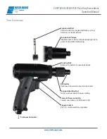
Insert the desired screwdriver bit into the quick change holder of the driver bit by pulling the outer sleeve of the bit
holder to release the retainer. Insert an appropriate power bit, release the sleeve and ensure that the bit is properly
locked in place by pulling back and forth on the bit.
Make sure that the tool’s start trigger is not engaged to prevent the tool from accidentally starting when turning
on the controller’s power switch. Turn the controller’s main power switch on. Select the desired speed (Hi/Lo) of the
screwdriver via the speed switch on the controller.
Grip the screwdriver so that the index finger is comfortably over the trigger mechanism and the thumb can be used
to change the position of the FWD/REV switch if required. Hold securely to prevent the screwdriver from rotating in
your hand during use. Familiarize yourself with the operation of the tool by free running the tool before use at higher
torque values.
Align the driver bit properly with the head of the fastener. Keeping the driver in-line with the fastener, activate and
hold the start trigger. The screwdriver will install the fastener (FWD). When the preset torque is reached, the clutch will
activate and the tool will shut off. Once the tool shuts off, release the trigger to reset. To stop the screwdriver before
fastening is complete, release the trigger.
To remove a fastener, change the FWD/REV switch to the REV position. Press the start mechanism to run the driver
in reverse (CCW). Do not switch the direction while the motor is running. A protection circuit will stop the tool if it is
inadvertently switched while running — if this happens, the trigger must be released and reactivated to continue
operating.
An external torque adjustment nut located at the nose of the screwdriver is used to set the output torque of the
screwdriver. A reference scale (0–8) is available as a guide — this scale is for reference only and does not indicate
actual torque values. Rotate the torque nut clockwise to increase torque output, CCW to decrease torque output. Make
the torque adjustment through a series of gradual increases, starting below the desired torque level. We recommend
the use of an appropriate torque tester and static joint testing after installation to verify proper torque settings.
Once the torque is set, remove the housing nut and cover the torque adjustment nut with the included torque lock
sleeve to avoid accidental torque adjustments.
The torque output of the screwdriver should be verified on a regular basis. Frequency of verification will depend on
the customer’s specific application and quality control requirements. During the initial screwdriver break-in period,
output torque may decay somewhat as the mechanical components wear in.
Operating the screwdriver
Setting the torque


