


Local Inputs Tab
Page 25 of 67
eZV-440 Version 2.1 Application Guide
Document Edition 2.5
3.
Click the “+” sign at the end of the row.
•
In the DemandVentEnable field, select Enabled if you are using demand
controlled ventilation with the CO
2
sensors.
•
In the CO2DemandVentSetpoint field, enter the CO
2
demand ventilation setpoint.
CO
2
levels higher than this setpoint will maintain the demand for ventilation.
For more information about demand control ventilation, go to page
Set Up Damper Feedback
Damper feedback signals can be configured on the controller input 5. The actuator must have a
position feedback feature.
To set up damper feedback:
1.
Make sure the actuator is connected to the controller via the actuator connector.
2.
Next to input number 5, in the Function field, select Damper1Feedback_.
If a tristate output is assigned to a damper, the algorithm will use this feedback signal
rather than a calculated damper position based on runtime.
3.
In the Action/Scale Range field, select the input scale range that matches your damper
feedback signal. If you do not select a scale range, the default scale range is assumed to
be zero to full scale 0 to 100%.
Set Up Other Supporting Inputs
This topic describes how to set up supporting inputs like fan status and window monitoring
using the Local Inputs tab in the configuration graphic.
To set up these options:
1.
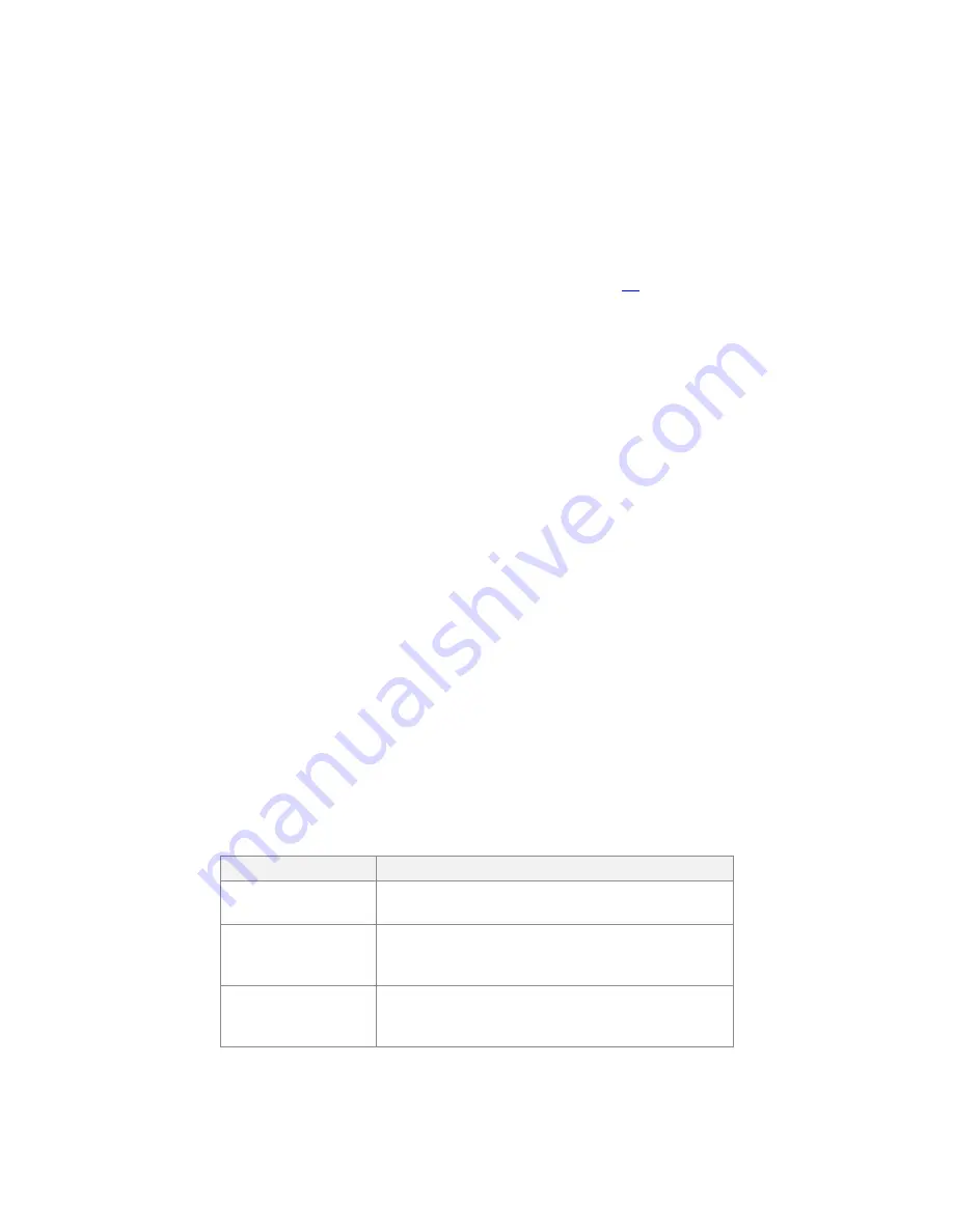
Next to the input number that you’ve assigned to the sensor, in the Function field, select
one or more of the following options and their associated action:
Function
Select this option if you are:
FanStatus
Adding a current or airflow switch that detects when
the zone supply fan is running.
AnalogMUX
Creating an analog input that will be used for
monitoring and will not be used by the algorithm in
the controller.
BinaryMUX
Creating a binary input that will be used for
monitoring and will not be used by the algorithm in
the controller.


