Display Assembly
59
5
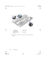
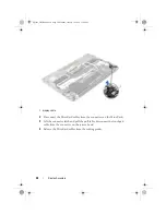
Remove the four screws (two on each side) that secure the display
assembly to the palm-rest assembly.
6
Gently lift the palm-rest assembly at a 90-degree angle and then release
the palm-rest assembly off the display assembly.
1 routing guides
2 touchpad cable
3 Mini-Card cables (2)
1
3
2
Spyder_OM_Book.book Page 59 Monday, January 16, 2012 11:02 AM
Содержание XPS 13
Страница 8: ...8 Contents Spyder_OM_Book book Page 8 Monday January 16 2012 11 02 AM ...
Страница 12: ...12 Before you Begin Spyder_OM_Book book Page 12 Monday January 16 2012 11 02 AM ...
Страница 30: ...30 Solid State Drive Spyder_OM_Book book Page 30 Monday January 16 2012 11 02 AM ...
Страница 44: ...44 I O Board Spyder_OM_Book book Page 44 Monday January 16 2012 11 02 AM ...
Страница 50: ...50 System Board Spyder_OM_Book book Page 50 Monday January 16 2012 11 02 AM ...
Страница 56: ...56 Keyboard Spyder_OM_Book book Page 56 Monday January 16 2012 11 02 AM ...
Страница 62: ...62 Display Assembly Spyder_OM_Book book Page 62 Monday January 16 2012 11 02 AM ...
Страница 66: ...66 Palm Rest Assembly Spyder_OM_Book book Page 66 Monday January 16 2012 11 02 AM ...


