


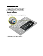


Installing the Battery
1.
Place the battery into its slot until it clicks into place.
2.
Connect the battery cable to its connector on the system board.
3.
Install the base cover.
4.
Follow the procedures in
After Working Inside Your Computer.
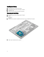
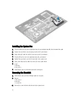
Removing the Hard Drive
1.
Follow the procedures in
Before Working Inside Your Computer
.
2.
Remove:
a) base cover
b) battery
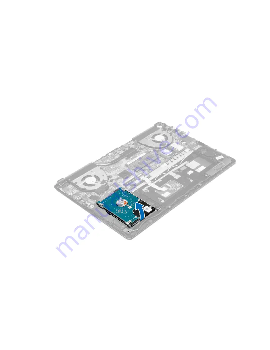
3.
Lift the hard drive assembly in an upward direction to release it from its compartment on the computer.
4.
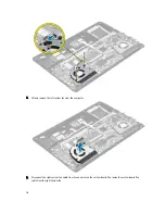
Lift and remove the hard drive from the computer..
12
Содержание Vostro 5470
Страница 1: ...Dell Vostro 5470 Owner s Manual Regulatory Model P41G Regulatory Type P41G002 ...
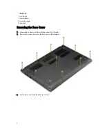
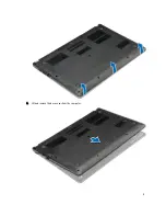
Страница 9: ...4 Lift and remove the base cover from the computer 9 ...
Страница 11: ...5 Lift and remove the battery from the computer 11 ...
Страница 19: ...4 Lift up the heatsink and remove from the computer 19 ...
Страница 22: ...5 Remove the system board from the computer 22 ...
Страница 24: ...4 Lift the speaker assembly along with the routing cable and remove the speakers from the computer 24 ...
Страница 29: ...6 Pry along the inner edges of the display bezel and remove the display bezel 29 ...
Страница 44: ...44 ...


