background image

4. Install the:

a)

Cover

5. Follow the procedure in 

After working inside your computer

.

Memory modules

Removing memory module

1. Follow the procedure in 

Before working inside your computer

.

2. Remove the:

a)

Cover

3. To remove the memory module:

a) Push the memory module retention tabs on both sides of the memory module.
b) Lift the memory module from the memory module connector on the system board.

Removing and installing components

39

Содержание Vostro 3671

Страница 1: ...Dell Vostro 3671 Service Manual Regulatory Model D19M Regulatory Type D19M005 ...

Страница 2: ...age to hardware or loss of data and tells you how to avoid the problem WARNING A WARNING indicates a potential for property damage personal injury or death 2019 2020 Dell Inc or its subsidiaries All rights reserved Dell EMC and other trademarks are trademarks of Dell Inc or its subsidiaries Other trademarks may be trademarks of their respective owners 2019 08 Rev A00 ...

Страница 3: ...9 Installing 3 5 inches hard drive assembly optional 22 Removing the 2 5 inches hard drive assembly optional 25 Installing 2 5 inches hard drive assembly optional 28 Removing the M 2 PCIe Solid State Drive optional 31 Installing the M 2 PCIe SSD optional 32 Optical drive 33 Removing optical drive assembly 33 Installing optical drive assembly 35 WLAN card 37 Removing WLAN card 37 Installing WLAN Ca...

Страница 4: ...ving the coin cell battery 64 Installing the coin cell battery 65 Processor 66 Removing the processor 66 Installing the processor 67 System board 68 Removing the system board 68 Installing the system board 74 4 Troubleshooting 79 Enhanced Pre Boot System Assessment ePSA diagnostics 79 Running the ePSA Diagnostics 79 Diagnostics 79 Diagnostic error messages 80 System error messages 83 5 Getting hel...

Страница 5: ...cally touching an unpainted metal surface that is grounded to ground yourself before you touch the computer to perform any disassembly tasks CAUTION Handle components and cards with care Do not touch the components or contacts on a card Hold a card by its edges or by its metal mounting bracket Hold a component such as a processor by its edges not by its pins CAUTION When you disconnect a cable pul...

Страница 6: ...ector on the back of the computer 7 Remove any installed ExpressCards or Smart Cards from the appropriate slots After working inside your computer After you complete any replacement procedure ensure that you connect external devices cards and cables before turning on your computer CAUTION To avoid damage to the computer use only the battery designed for this particular Dell computer Do not use bat...

Страница 7: ...TV to optimize picture settings based on content type Additional Color Spaces Adds support for additional color models used in digital photography and computer graphics 4K Support Enables video resolutions far beyond 1080p supporting next generation displays that will rival the Digital Cinema systems used in many commercial movie theaters HDMI Micro Connector A new smaller connector for phones and...

Страница 8: ...efined by the latest USB 3 0 USB 3 1 Gen 1 specification They are Super Speed Hi Speed and Full Speed The new SuperSpeed mode has a transfer rate of 4 8Gbps While the specification retains Hi Speed and Full Speed USB mode commonly known as USB 2 0 and 1 1 respectively the slower modes still operate at 480Mbps and 12Mbps respectively and are kept to maintain backward compatibility USB 3 0 USB 3 1 G...

Страница 9: ...erritory like external RAID storage systems Listed below are some of the available SuperSpeed USB 3 0 USB 3 1 Gen 1 products External Desktop USB 3 0 USB 3 1 Gen 1 Hard Drives Portable USB 3 0 USB 3 1 Gen 1 Hard Drives USB 3 0 USB 3 1 Gen 1 Drive Docks Adapters USB 3 0 USB 3 1 Gen 1 Flash Drives Readers USB 3 0 USB 3 1 Gen 1 Solid state Drives USB 3 0 USB 3 1 Gen 1 RAIDs Optical Media Drives Multi...

Страница 10: ... screws 2 4 Screw list and images Table 2 Vostro 3671screw size list Component Screw type Quanti ty Image Color Power supply unit Side cover I O bracket Systemboard PCIe bracket 6 32xL6 35 4 2 1 8 1 Black 3 5 Hard drive Optional 6 32UNCx3 6 4 Silver Optical drive M2x2 2 Black M 2 SSD card NGFF card WLAN card M2x3 5 1 1 1 Silver 2 5 Hard drive optional 1 pcs 2 5 Hard drive optional 2 pcs M3x3 5 2 4...

Страница 11: ...HDD_ODD_PowerCable Connector SATA_PWR 8 HDD_ODD_PowerCable Connector SATA_PWR 9 ATX Power Connector ATX_SYS 10 M 2 WLAN Connector 11 Service mode password clear CMOS clear jumpers 12 PCI Connector SLOT4 13 PCI e X1 Connector SLOT3 14 PCI e X16 Connector SLOT2 15 PCI e X1 Connector SLOT1 16 M 2 PCIe Connector 17 CPU Power Connector ATX_CPU 18 Processor Socket CPU Removing and installing components ...

Страница 12: ...moving the cover 1 Follow the procedure in Before working inside your computer 2 To remove the cover a Remove the two 6 32x6 35 screws that secure the cover to the computer 1 and pull the cover away from the system 2 b Lift the cover 12 Removing and installing components ...

Страница 13: ...Installing the cover 1 Place the cover on the computer and slide the cover forward until the latches snap in 1 Removing and installing components 13 ...

Страница 14: ...2 Tighten the two 6 32x6 35 screws to secure the cover to the computer 2 14 Removing and installing components ...

Страница 15: ... Follow the procedure in Before working inside your computer 2 Remove the Cover 3 To remove the bezel a Lift the three latches to release the bezel from the chassis 1 b Lift the chassis rotate and pull the front bezel away from the computer to release the tabs 2 Removing and installing components 15 ...

Страница 16: ...c Lift the chassis and remove the front bezel from the chassis 16 Removing and installing components ...

Страница 17: ...Installing the front bezel 1 Position the bezel to align the tab holders on the chassis 1 Removing and installing components 17 ...

Страница 18: ...2 Rotate the bezel until the tabs clicks into place 2 18 Removing and installing components ...

Страница 19: ...g 3 5 inches hard drive assembly optional 1 Follow the procedure in Before working inside your computer 2 Remove the a Cover b Front bezel 3 To remove the hard drive assembly a Disconnect the hard drive data and power cables from the connectors on the hard drive Removing and installing components 19 ...

Страница 20: ...b Remove the four 6 32x3 6 screws that secure the hard drive assembly to the base and front of the chassis 20 Removing and installing components ...

Страница 21: ...c Slide and lift the HDD away from the chassis Removing and installing components 21 ...

Страница 22: ...Installing 3 5 inches hard drive assembly optional 1 Insert the hard drive assembly into the slot on the computer until it clicks into place 22 Removing and installing components ...

Страница 23: ...2 Install the four 6 32x3 6 screws that secure the hard drive assembly to the base and front of the chassis Removing and installing components 23 ...

Страница 24: ...3 Connect the hard drive cable and the power cable to the connectors on the hard drive 24 Removing and installing components ...

Страница 25: ...ng the 2 5 inches hard drive assembly optional 1 Follow the procedure in Before working inside your computer 2 Remove the a Cover b Front bezel 3 To remove the hard drive assembly a Disconnect the hard drive data and power cables from the connectors on the hard drive Removing and installing components 25 ...

Страница 26: ...b Remove the two M3x3 5 screws that secure the hard drive assembly to the front of the chassis 26 Removing and installing components ...

Страница 27: ...c Slide and lift the HDD away from the chassis Removing and installing components 27 ...

Страница 28: ...Installing 2 5 inches hard drive assembly optional 1 Place the hard drive assembly into the chassis 28 Removing and installing components ...

Страница 29: ...2 Install the two M3x3 5 screws that secure the hard drive assembly to the base and front of the chassis Removing and installing components 29 ...

Страница 30: ...3 Connect the SATA cable and the power cable to the connectors on the hard drive 30 Removing and installing components ...

Страница 31: ...CIe Solid State Drive optional 1 Follow the procedure in Before working inside your computer 2 Remove the Cover 3 To remove the Solid State Drive SSD a Remove the one M2x3 5 screw that secures the SSD to the system board 1 b Slide the SSD from the connector on the system board 2 Removing and installing components 31 ...

Страница 32: ...stalling the M 2 PCIe SSD optional 1 Insert the SSD into the connector on the system board 1 2 Replace the one M2x3 5 screw that secures the SSD to the system board 2 32 Removing and installing components ...

Страница 33: ...ove the a Cover 3 To remove the slim optical drive a Disconnect the data cable and power cable from the connectors on the optical drive assembly 1 NOTE You must unroute the cables from the tabs under the drive cage to allow you to disconnect the cables from the connectors b Remove the two M2x2 screws that secure the optical drive assembly to the computer 2 Removing and installing components 33 ...

Страница 34: ...c Slide the optical drive assembly out of the computer 34 Removing and installing components ...

Страница 35: ...Installing optical drive assembly 1 Place the optical drive into the optical drive slot Removing and installing components 35 ...

Страница 36: ...ure the optical drive assembly to the computer 1 3 Route the data cable and power cable under the drive cage 4 Connect the data cable and power cable to the connectors on the optical drive assembly 2 36 Removing and installing components ...

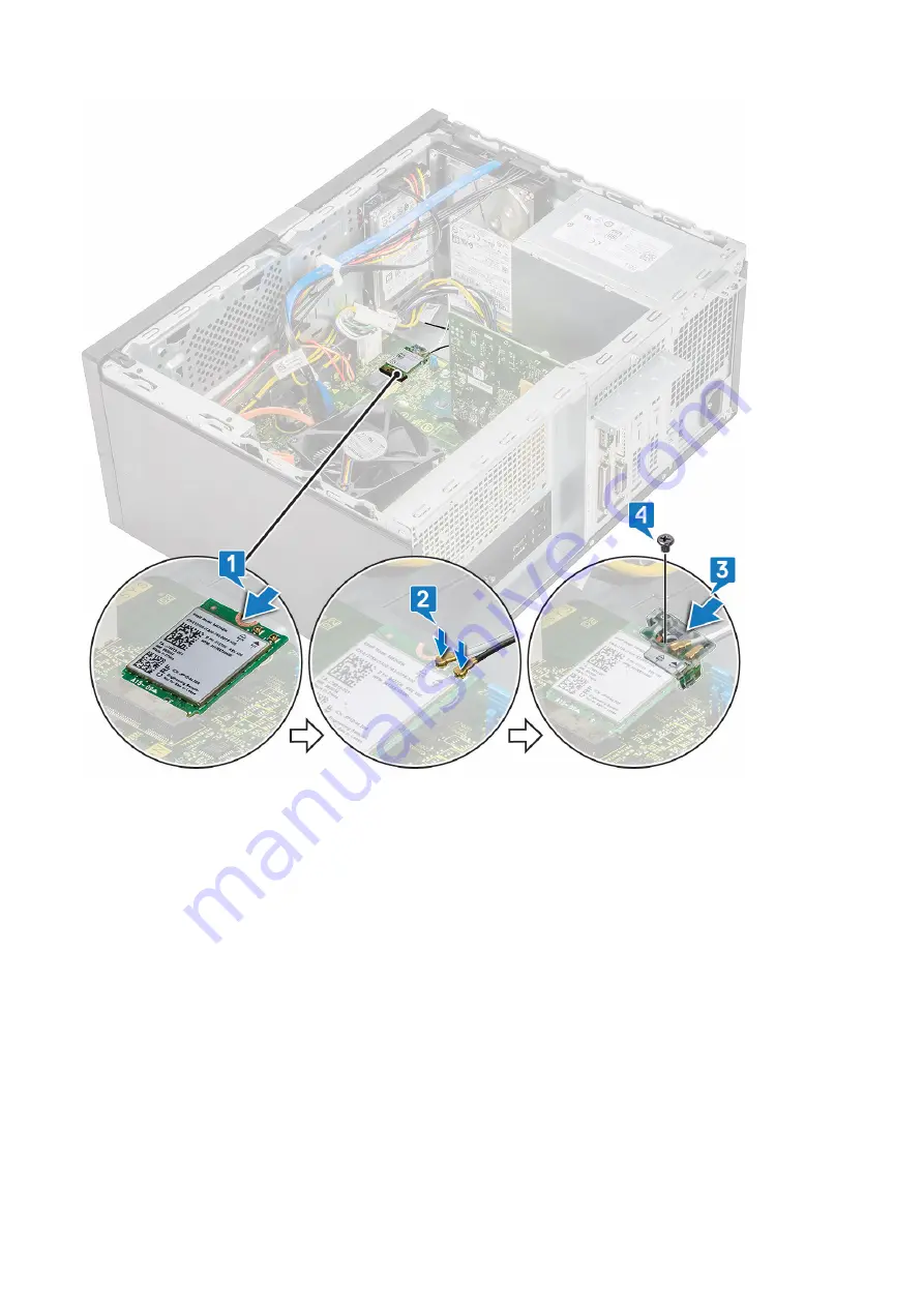
Страница 37: ...uter 2 Remove the a Cover 3 To remove the WLAN card a Loosen one M2x3 5 screw to release the plastic tab that secures the WLAN card to the computer 1 b Remove the plastic tab to access the WLAN cables 2 c Disconnect the WLAN cables from the connectors on the WLAN card 3 d Lift the WLAN card from the connector on the system board 4 Removing and installing components 37 ...

Страница 38: ... connector on the system board 1 2 Connect the WLAN cables to the connectors on the WLAN card 2 3 Place the plastic tab on the WLAN card 3 and tighten one M2x3 5 screw to secure the WLAN card to the system board 4 38 Removing and installing components ...

Страница 39: ...ry module 1 Follow the procedure in Before working inside your computer 2 Remove the a Cover 3 To remove the memory module a Push the memory module retention tabs on both sides of the memory module b Lift the memory module from the memory module connector on the system board Removing and installing components 39 ...

Страница 40: ...tabs click into place 3 Install the a Cover 4 Follow the procedure in After working inside your computer Expansion card Removing the PCIe expansion card 1 Follow the procedure in Before working inside your computer 2 Remove the a Cover 3 To remove the PCIe expansion card a Remove the one 6 32x6 35 screw to remove the PCIe bracket 1 2 40 Removing and installing components ...

Страница 41: ...b Push the release tab 1 and lift the PCIe expansion card out of the computer 2 Removing and installing components 41 ...

Страница 42: ...Installing the PCIe expansion card 1 Pull the release latch backward to open 2 Insert the PCIe expansion card to the connector on the system board 42 Removing and installing components ...

Страница 43: ...the PCIe expansion card by pushing the card retention latch until it clicks into place 4 Close the PCIe bracket 1 5 Replace the one 6 32x6 35 screw to fix the PCIe bracket 2 Removing and installing components 43 ...

Страница 44: ... your computer Optional card Removing the optional card 1 Follow the procedure in Before working inside your computer 2 Remove the a Cover 3 To remove the optional card a Remove the one 6 32x6 35 screw to remove the PCIe bracket 1 2 44 Removing and installing components ...

Страница 45: ...b Lift the optional card out of the computer Removing and installing components 45 ...

Страница 46: ...Installing the optional card 1 Insert the optional card to the connector on the system board 46 Removing and installing components ...

Страница 47: ...2 Close the PCIe bracket 1 3 Replace the one 6 32x6 35 screw to fix the PCIe bracket 2 Removing and installing components 47 ...

Страница 48: ...ower supply unit Removing power supply unit 1 Follow the procedure in Before working inside your computer 2 Remove the a Cover b Cooling shroud 3 Removing the Power supply unit PSU a Disconnect the PSU cables from the connectors on the system board 48 Removing and installing components ...

Страница 49: ...b Unroute the PSU cables from the retention clips 1 2 3 Removing and installing components 49 ...

Страница 50: ...the PSU cable from the metal clip 1 press the tab of the 8 pin power cables and disconnect it from the system board 2 and then remove 4 6 32x6 35 screws to release the PSU 3 50 Removing and installing components ...

Страница 51: ...d Press the metal release tab slide the PSU toward the back and lift it out of the computer Removing and installing components 51 ...

Страница 52: ...Installing power supply unit 1 Insert the power supply unit PSU into the PSU slot and slide it toward the back of the computer until it clicks into place 52 Removing and installing components ...

Страница 53: ...2 Tighten the four 6 32x6 35 screws to secure the PSU to the computer 1 route the PSU cable from the metal clip 2 and insert the 8 pin power cables 3 Removing and installing components 53 ...

Страница 54: ...3 Route the PSU cables through the retention tabs 1 2 3 54 Removing and installing components ...

Страница 55: ...4 Connect the PSU cables to the connectors on the system board Removing and installing components 55 ...

Страница 56: ...ur computer Cooling shroud Removing the cooling shroud 1 Follow the procedure in Before working inside your computer 2 Remove the a Cover 3 To remove the cooling shroud a Pry and release the tabs that secure the cooling shroud to the process fan 1 2 3 56 Removing and installing components ...

Страница 57: ...b Lift the cooling shroud away from the computer Removing and installing components 57 ...

Страница 58: ... the tabs on the cooling shroud with the securing slots on the computer NOTE Make sure the cooling shroud is placed such that the REAR mark on the cooling shroud is towards the rear side of the system 58 Removing and installing components ...

Страница 59: ...2 Lower the cooling shroud into the chassis and press down on the shroud until it snaps into place 1 2 3 Removing and installing components 59 ...

Страница 60: ...at sink assembly Removing the heat sink assembly 1 Follow the procedure in Before working inside your computer 2 Remove the a Cover b Cooling shroud 3 To remove the heat sink assembly a Disconnect the fan cable from the connector on the system board 60 Removing and installing components ...

Страница 61: ... order marked on the system board NOTE Remove the screws that secure the heat sink to the system board in the order of the callouts shown 1 2 3 4 c Lift the heat sink assembly away from the computer Removing and installing components 61 ...

Страница 62: ...bly with screw holders on the system board 2 Tighten the four M3 screws to secure the heat sink assembly to the computer and system board NOTE Tighten the screws on the system board in the order of the callout numbers 1 2 3 4 62 Removing and installing components ...

Страница 63: ...3 Connect the fan cable to the connector on the system board Removing and installing components 63 ...

Страница 64: ... Removing the coin cell battery 1 Follow the procedure in Before working inside your computer 2 Remove the Cover 3 To remove the coin cell battery a Press the side of the battery that allows the battery to pop up from the socket 1 b Lift the coin cell battery out of the computer 2 64 Removing and installing components ...

Страница 65: ...Installing the coin cell battery 1 Place the coin cell battery in its slot on the system board 1 2 Press the battery until it snaps back into place 2 Removing and installing components 65 ...

Страница 66: ...ink assembly 3 To remove the processor a Press the release lever down and then move it outward to release it from the retention hook 1 CAUTION The processor socket pins are fragile and can be permanently damaged Be careful not to bend the pins in the processor socket when removing the processor out of the socket b Lift the processor cover and remove the processor from the socket 2 3 66 Removing an...

Страница 67: ... 1 on the cpu with pin 1 on the motherboard CAUTION Do not use force to seat the processor When the processor is positioned correctly it engages easily into the socket 2 Lower the processor cover 2 3 Press the release lever down and then move it inward to secure it with the retention hook 3 Removing and installing components 67 ...

Страница 68: ...e in After working inside your computer System board Removing the system board 1 Follow the procedure in Before working inside your computer 2 Remove the a Cover b Front bezel c Hard drive d WLAN e Memory module f Expansion card g Cooling shroud 68 Removing and installing components ...

Страница 69: ...tem board 1 b Remove the one 6 32x6 35 screw that secures the I O panel cover to the computer 2 c Slide the I O panel cover 3 4 Unroute and disconnect the hard drive power cable hard drive data cable optical drive power cable power supply unit cable 1 2 3 4 5 Removing and installing components 69 ...

Страница 70: ...5 To remove the system board a Remove the eight 6 32x6 35 screws and one 6 32x4 8 screw for M2 SSD that secure the system board to the computer 1 2 70 Removing and installing components ...

Страница 71: ...Removing and installing components 71 ...

Страница 72: ...b Tilt the system board at 45 degrees and then lift the system board out of the computer 72 Removing and installing components ...

Страница 73: ...Removing and installing components 73 ...

Страница 74: ...Installing the system board 1 Align the system board to the port connectors on the rear of the chassis and place the system board in the chassis 74 Removing and installing components ...

Страница 75: ...2 Tighten the eight 6 32x6 35 screws and one 6 32x4 8 screw for M2 SSD that secures the system board to the chassis Removing and installing components 75 ...

Страница 76: ...3 Connect the hard drive optical drive power supply unit cable route the cables and speaker cables 1 2 3 4 5 to the system board 76 Removing and installing components ...

Страница 77: ...4 Place the I O port bracket 1 and tighten the screw 6 32x6 35 2 and connect the cable to the system board 3 Removing and installing components 77 ...

Страница 78: ...a Processor b Heat sink assembly c Cooling shroud d Expansion card e Memory module f WLAN g SSD h Front bezel i Cover 6 Follow the procedure in After working inside your computer 78 Removing and installing components ...

Страница 79: ...In the boot menu screen use Up Down arrow key to select the Diagnostics option and then press Enter NOTE The Enhanced Pre boot System Assessment window displays listing all devices detected in the computer The diagnostics starts running the tests on all the detected devices 4 Press the arrow in the lower right corner to go to the page listing The detected items are listed and tested 5 To run a dia...

Страница 80: ... The primary cache internal to the microprocessor has failed Contact Dell CD DRIVE CONTROLLER FAILURE The optical drive does not respond to commands from the computer DATA ERROR The hard drive cannot read the data DECREASING AVAILABLE MEMORY One or more memory modules may be faulty or improperly seated Reinstall the memory modules or if necessary replace them DISK C FAILED INITIALIZATION The hard ...

Страница 81: ... Hard Disk Drive tests in Dell Diagnostics INSERT BOOTABLE MEDIA The operating system is trying to boot to non bootable media such as an optical drive Insert bootable media INVALID CONFIGURATION INFORMATION PLEASE RUN SYSTEM SETUP PROGRAM The system configuration information does not match the hardware configuration The message is most likely to occur after a memory module is installed Correct the...

Страница 82: ...dows error checking utility to check the file structure on the hard drive See Windows Help and Support for instructions click Start Help and Support If a large number of sectors are defective back up the data if possible and then format the hard drive SEEK ERROR The operating system cannot find a specific track on the hard drive SHUTDOWN FAILURE A chip on the system board may be malfunctioning Run...

Страница 83: ... the cable does not solve the problem replace the keyboard No boot device available No bootable partition on hard disk drive the hard disk drive cable is loose or no bootable device exists If the hard drive is your boot device ensure that the cables are connected and that the drive is installed properly and partitioned as a boot device Enter system setup and ensure that the boot sequence informati...

Страница 84: ...ne based support and service options Availability varies by country and product and some services may not be available in your area To contact Dell for sales technical support or customer service issues 1 Go to Dell com support 2 Select your support category 3 Verify your country or region in the Choose a Country Region drop down list at the bottom of the page 4 Select the appropriate service or s...

Отзывы: