background image


20.

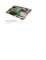
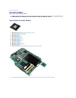
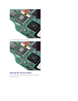
Remove the heat sink from the system board.  


Replacing the Processor Module 

Perform the above steps in the reverse order to replace the processor module. 

Back to Contents Page


Содержание Vostro 1014

Страница 1: ...soft Windows Windows Vista and the Windows Vista start button are either trademarks or registered trademarks of Microsoft Corporation in the United States and or other countries Adobe the Adobe logo and Adobe Flash Player are trademarks of Adobe Systems Incorporated Other trademarks and trade names may be used in this document to refer to either the entities claiming the marks and names or their p...

Страница 2: ...our Computer 2 Remove the battery from the computer 3 Remove the six screws that secure the access panel to the computer WARNING Before working inside your computer read the safety information that shipped with your computer For additional safety best practices information see the Regulatory Compliance Homepage at www dell com regulatory_compliance ...

Страница 3: ...4 Remove the access panel from the computer Replacing the Access Panel Perform the above steps in the reverse order to replace the access panel Back to Contents Page ...

Страница 4: ...urn the computer upside down with the back of the computer facing you 3 Slide the battery latches apart to the unlock position WARNING Before working inside your computer read the safety information that shipped with your computer For additional safety best practices information see the Regulatory Compliance Homepage at www dell com regulatory_compliance ...

Страница 5: ...3 Lift the battery from the computer Replacing the Battery Perform the above steps in the reverse order to replace the battery Back to Contents Page ...

Страница 6: ...rd drive 5 Remove the WLAN card 6 Remove the control panel cover 7 Remove the keyboard 8 Remove the display assembly 9 Remove the palm rest 10 Remove the I O board 11 Disconnect the Bluetooth card cable from the connector on the system board WARNING Before working inside your computer read the safety information that shipped with your computer For additional safety best practices information see t...

Страница 7: ...oth card cable from its routing groove and lift the Bluetooth card to remove it from the computer Replacing the Bluetooth Card Perform the above steps in the reverse order to replace the Bluetooth card Back to Contents Page ...

Страница 8: ...the hard drive 5 Remove the WLAN card 6 Remove the control panel cover 7 Remove the keyboard 8 Remove the display assembly 9 Remove the palm rest 10 Pull the coin cell battery from the plastic sleeve WARNING Before working inside your computer read the safety information that shipped with your computer For additional safety best practices information see the Regulatory Compliance Homepage at www d...

Страница 9: ...able from the connector on the system board then lift the coin cell battery to remove it from the computer Replacing the Coin Cell Battery Perform the above steps in the reverse order to replace the coin cell battery Back to Contents Page ...

Страница 10: ...three control panel cover screws from the bottom of the computer 4 Insert a plastic scribe to release the four control panel cover clips located inside the battery well WARNING Before working inside your computer read the safety information that shipped with your computer For additional safety best practices information see the Regulatory Compliance Homepage at www dell com regulatory_compliance V...

Страница 11: ...nel cover from the computer Replacing the Control Panel Cover Perform the above steps in the reverse order to replace the control panel cover Vostro 1015 Removing the Control Panel Cover 1 Follow the procedures in Before Working Inside Your Computer 2 Remove the battery ...

Страница 12: ...emove the eight control panel cover screws from the bottom of the computer 4 Turn the computer over and open the display 5 Remove the control panel cover from the computer Replacing the Control Panel Cover ...

Страница 13: ...Perform the above steps in the reverse to replace the control panel cover Back to Contents Page ...

Страница 14: ... Remove the WLAN card 6 Remove the control panel cover 7 Remove the keyboard 8 Remove the display assembly 9 Remove the palm rest 10 Disconnect the processor fan cable from the connector on the system board WARNING Before working inside your computer read the safety information that shipped with your computer For additional safety best practices information see the Regulatory Compliance Homepage a...

Страница 15: ...11 Remove the screw that secures the processor fan to the computer 12 Lift the processor fan from the computer ...

Страница 16: ...Replacing the Processor Fan Perform the above steps in the reverse order to replace the processor fan Back to Contents Page ...

Страница 17: ...r Computer 2 Press the ExpressCard to release it from its slot in the computer 3 Slide the ExpressCard from the computer WARNING Before working inside your computer read the safety information that shipped with your computer For additional safety best practices information see the Regulatory Compliance Homepage at www dell com regulatory_compliance ...

Страница 18: ...Replacing the ExpressCard Perform the above steps in the reverse order to replace the ExpressCard Back to Contents Page ...

Страница 19: ...rive assembly to the computer WARNING Before working inside your computer read the safety information that shipped with your computer For additional safety best practices information see the Regulatory Compliance Homepage at www dell com regulatory_compliance Removing the Hard Drive Assembly Replacing the Hard Drive Assembly Removing the Hard Drive Bracket Replacing the Hard Drive Bracket Removing...

Страница 20: ...the hard drive assembly from the computer Replacing the Hard Drive Assembly Perform the above steps in the reverse order to replace the hard drive assembly in the computer Removing the Hard Drive Bracket 1 Follow the procedures in Before Working Inside Your Computer 2 Remove the battery 3 Remove the access panel 4 Remove the hard drive ...

Страница 21: ...5 Remove the four screws two on either sides of the bracket that secure the hard drive to the hard drive bracket 6 Lift the bracket from the hard drive Replacing the Hard Drive Bracket ...

Страница 22: ...llow the procedures in Before Working Inside Your Computer 2 Remove the battery 3 Remove the access panel 4 Remove the hard drive 5 Tugging gently remove the hard drive interposer from the hard drive Replacing the Hard Drive Interposer Perform the above steps in the reverse order to replace the hard drive interposer Back to Contents Page ...

Страница 23: ...move the keyboard 11 Remove the display assembly 12 Remove the palm rest 13 Remove the processor fan 14 Remove the I O board 15 Remove the Bluetooth wireless card 16 Remove the system board and place the system board on a clean dry surface 17 Use the marked sequence in the illustration below to loosen the four screws that secure the heat sink to the system board WARNING Before working inside your ...

Страница 24: ...18 Remove the heat sink from the system board Replacing the Heat Sink Perform the above steps in the reverse order to replace the heat sink Back to Contents Page ...

Страница 25: ...move the WLAN card 6 Remove the control panel cover 7 Remove the keyboard 8 Remove the display assembly 9 Remove the palm rest 10 Remove the two screws that secure the I O board to the computer chassis WARNING Before working inside your computer read the safety information that shipped with your computer For additional safety best practices information see the Regulatory Compliance Homepage at www...

Страница 26: ...e modem cable from the connector on the I O board 12 Lift the I O board to remove it from the computer Replacing the I O Board Perform the above steps in the reverse order to replace the I O board Back to Contents Page ...

Страница 27: ...Remove the control panel cover 4 Remove the two screws that secure the keyboard to the computer 5 Flip the keyboard over and lay it on the palm rest WARNING Before working inside your computer read the safety information that shipped with your computer For additional safety best practices information see the Regulatory Compliance Homepage at www dell com regulatory_compliance ...

Страница 28: ... keyboard data clip to release the keyboard cable from the connector on the system board 7 Remove the keyboard from the computer NOTE Lift the keyboard carefully to ensure that you do not pull on the keyboard cable ...

Страница 29: ...Replacing the Keyboard Perform the above steps in the reverse order to replace the keyboard Back to Contents Page ...

Страница 30: ...es WARNING Before working inside your computer read the safety information that shipped with your computer For additional safety best practices information see the Regulatory Compliance Homepage at www dell com regulatory_compliance Removing the Display Assembly Replacing the Display Assembly Removing the Display Bezel Replacing the Display Bezel Removing the LED Display Panel Replacing the LED Di...

Страница 31: ...emove the two screws that secure the display assembly to the bottom of the base of the computer 10 Turn the computer right side up and open the display 11 Remove the wireless cable from the routing guides ...

Страница 32: ...connect the display inverter cable 13 Remove the two screws that secure the display assembly to the top of the base of the computer 14 Lift the display assembly from the computer Ensure that all the cables are carefully removed away from the computer ...

Страница 33: ...the display assembly Removing the Display Bezel 1 Follow the procedures in Before Working Inside Your Computer 2 Remove the battery 3 Remove the access panel 4 Remove the hard drive 5 Remove the WLAN card 6 Remove the control panel cover 7 Remove the keyboard 8 Remove the display assembly ...

Страница 34: ...9 Using a plastic scribe remove the six rubber screw covers from the display assembly 10 Remove the six screws from the display assembly ...

Страница 35: ...er to replace the display bezel into the display assembly Removing the Display LED Panel 1 Follow the procedures in Before Working Inside Your Computer 2 Remove the battery 3 Remove the access panel 4 Remove the hard drive 5 Remove the WLAN card 6 Remove the control panel cover 7 Remove the keyboard ...

Страница 36: ...8 Remove the display assembly 9 Remove the display bezel 10 Remove the four screws that secure the display panel to the display assembly 11 Disconnect the display camera cable ...

Страница 37: ...isplay LED panel Removing the Display Camera 1 Follow the procedures in Before Working Inside Your Computer 2 Remove the battery 3 Remove the access panel 4 Remove the hard drive 5 Remove the WLAN card 6 Remove the control panel cover 7 Remove the keyboard 8 Remove the display assembly 9 Remove the display bezel 10 Remove the display LED panel ...

Страница 38: ...e steps in the reverse order to replace the display camera into its bracket and from there to the display assembly Removing the Display Inverter Cable 1 Follow the procedures in Before Working Inside Your Computer 2 Remove the battery 3 Remove the access panel 4 Remove the hard drive 5 Remove the WLAN card 6 Remove the control panel cover 7 Remove the keyboard 8 Remove the display assembly 9 Remov...

Страница 39: ...ra to the display LED panel 12 Carefully detach and remove the display inverter cable from the display LED panel Replacing the Display Inverter Cable Perform the above steps in the reverse order to replace the display inverter cable Back to Contents Page ...

Страница 40: ...move the WLAN card 9 Remove the control panel cover 10 Remove the keyboard 11 Remove the display assembly 12 Remove the palm rest 13 Remove the processor fan 14 Remove the I O board 15 Remove the Bluetooth wireless card 16 Disconnect the speaker cables from the system board WARNING Before working inside your computer read the safety information that shipped with your computer For additional safety...

Страница 41: ...17 Disconnect the power cable from the system board 18 Remove the five screws that secure the system board to the computer chassis ...

Страница 42: ... away from the computer chassis Replacing the System Board Perform the above steps in the reverse order to replace the system board Vostro 1015 Removing the System Board 1 Follow the procedures in Before Working Inside Your Computer ...

Страница 43: ...y modules 8 Remove the WLAN card 9 Remove the control panel cover 10 Remove the keyboard 11 Remove the display assembly 12 Remove the palm rest 13 Remove the processor fan 14 Remove the I O board 15 Remove the Bluetooth wireless card 16 Disconnect the speaker cables from the system board 17 Disconnect the power cable from the system board ...

Страница 44: ...18 Remove the six screws that secure the system board to the computer chassis 19 Lift the system board up and away from the computer chassis ...

Страница 45: ...Replacing the System Board Perform the above steps in the reverse order to replace the system board Back to Contents Page ...

Страница 46: ...lly spread apart the securing clips on each end of the first memory module connector until the first module pops up 5 Slide the first memory module from its socket and remove the module from the computer WARNING Before working inside your computer read the safety information that shipped with your computer For additional safety best practices information see the Regulatory Compliance Homepage at w...

Страница 47: ...ector with the tab in the connector slot 2 Slide the module firmly into the slot at a 45 degree angle and rotate the module down until it clicks into place If you do not feel the click remove the module and reinstall it 3 Replace the access panel 4 Replace the battery Back to Contents Page CAUTION Insert memory modules at a 45 degree angle to avoid damaging the connector ...

Страница 48: ...uter 2 Press the memory card to release it from the memory card slot in the computer 3 Slide the memory card from the computer WARNING Before working inside your computer read the safety information that shipped with your computer For additional safety best practices information see the Regulatory Compliance Homepage at www dell com regulatory_compliance ...

Страница 49: ...Replacing the Memory Card Perform the above steps in the reverse to replace a memory card Back to Contents Page ...

Страница 50: ...r 2 Remove the battery 3 Remove the screw that secures the optical drive to the computer 4 Remove the optical drive from the computer WARNING Before working inside your computer read the safety information that shipped with your computer For additional safety best practices information see the Regulatory Compliance Homepage at www dell com regulatory_compliance ...

Страница 51: ...Replacing the Optical Drive Perform the above steps in the reverse order to replace the optical drive Back to Contents Page ...

Страница 52: ...rive 6 Remove the WLAN card 7 Remove the control panel cover 8 Remove the keyboard 9 Remove the display assembly 10 From the bottom of the computer remove the screws that secure the palm rest to the computer WARNING Before working inside your computer read the safety information that shipped with your computer For additional safety best practices information see the Regulatory Compliance Homepage ...

Страница 53: ...11 Remove the screws that secure the palm rest to the computer in the media bay 12 Turn over the computer 13 Remove the screws that secure the palm rest to the computer ...

Страница 54: ...nect the control panel and palm rest cables from the system board 15 Lift the palm rest from the base of the computer Replacing the Palm Rest Perform the above steps in the reverse order to replace the palm rest ...

Страница 55: ...2 Remove the battery 3 Remove the optical drive 4 Remove the access panel 5 Remove the hard drive 6 Remove the WLAN card 7 Remove the control panel cover 8 Remove the keyboard 9 Remove the display assembly 10 From the bottom of the computer remove the screws that secure the palm rest to the computer ...

Страница 56: ...at secure the palm rest to the computer in the media bay 12 Turn the computer over 13 Remove the screws that secure the palm rest to the computer 14 Disconnect the control panel and palm rest cables from the system board ...

Страница 57: ...15 Lift the palm rest from the base of the computer Replacing the Palm Rest Perform the above steps in the reverse order to replace the palm rest Back to Contents Page ...

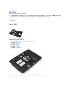
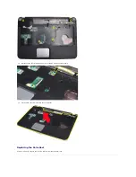
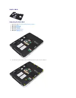
Страница 58: ... the display assembly 12 Remove the palm rest 13 Remove the processor fan 14 Remove the I O board 15 Remove the Bluetooth wireless card 16 Remove the system board 17 Remove the heat sink 18 Set aside the computer chassis and place the system board on a clean dry surface 19 Use a small flat blade screwdriver and rotate the ZIF socket cam screw counterclockwise until it comes to the cam stop WARNING...

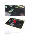
Страница 59: ...20 Remove the heat sink from the system board Replacing the Processor Module Perform the above steps in the reverse order to replace the processor module Back to Contents Page ...

Страница 60: ...he WLAN card 9 Remove the control panel cover 10 Remove the keyboard 11 Remove the display assembly 12 Remove the palm rest 13 Remove the processor fan 14 Remove the I O board 15 Remove the Bluetooth wireless card 16 Remove the system board 17 Remove the screw that secures the speaker to the computer chassis WARNING Before working inside your computer read the safety information that shipped with ...

Страница 61: ...18 Remove the speaker from the computer Replacing the Speaker Perform the above steps in the reverse order to replace the speaker Back to Contents Page ...

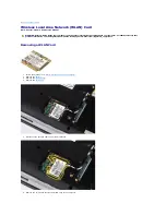
Страница 62: ...ttery 3 Remove the access panel 4 Remove the hard drive 5 Disconnect the antenna cables from the WLAN card 6 Remove the screw that secures the WLAN card to the computer WARNING Before working inside your computer read the safety information that shipped with your computer For additional safety best practices information see the Regulatory Compliance Homepage at www dell com regulatory_compliance ...

Страница 63: ...7 Slide the WLAN card out of the connector on the system board at a 45 degree angle Replacing a WLAN Card Perform the above steps in the reverse order to replace the WLAN card Back to Contents Page ...

Страница 64: ... l Using the boot menu l By pressing F2 Boot Menu 1 Turn on or restart your computer 2 When the Dell logo appears press F12 immediately 3 Highlight the option to enter System Setup and then press Enter F2 1 Turn on or restart your computer 2 When the Dell logo appears press F2 immediately If you are unable to enter System Setup by pressing the F2 key when the Dell Logo appears continue to wait unt...

Страница 65: ...rches for devices while trying to find an operating system to boot To change the boot order select the device to be changed in the list then click the up down arrows or use the keyboard PgUp PgDn keys to change the boot order of the device To remove devices for the boot list clear the check boxes Date Time Displays current date and time settings System Configuration Option Description NOTE The Sys...

Страница 66: ...llowed Performance Option Description Multi Core Support Use the check box to enable disable multi core support for the CPU Default setting Enabled Multi Core Support checked hard drive Acoustic Mode This option allows you to optimize your hard drive s performance and acoustic noise level based on your personal preferences Settings are Bypass Quiet and Performance Default setting Bypass Power Mana...

Страница 67: ...ugh Do not skip any steps in the boot process l Auto Allow the operating system to control this setting this works only when the operating system supports Simple Boot Flag Default setting Minimal Wireless Option Description Wireless Devices Use the check boxes to enable disable any available wireless devices The available options are Internal WLAN and Internal Bluetooth Default setting Enabled Mai...

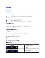
Страница 68: ...no lights appear the battery is in good condition and more than 80 percent of its original charge capacity remains Each light represents incremental degradation If five lights appear less than 60 percent of the charge capacity remains and you should consider replacing the battery Keyboard Status Lights The green lights located above the keyboard indicate the following LED Error Codes The following...

Страница 69: ...ed remove one and test Try the other module in the same slot and test Test the other slot with both modules 3 Replace the memory 4 Replace the system board OFF FLASH FLASH Modem error 1 Reseat the modem 2 Replace the modem 3 Replace the system board FLASH FLASH FLASH System board error 1 Replace the system board FLASH FLASH OFF Option ROM error 1 Reseat the device 2 Replace the device 3 Replace th...

Страница 70: ... to Contents Page ExpressCard Battery Access Panel Memory Control Panel Cover Display Assembly Processor Fan I O Board System Board Heat Sink Memory Card Optical Drive Hard Drive WLAN Card Keyboard Palm Rest Coin Cell Battery Internal Card with Bluetooth Wireless Technology Speaker Processor ...

Страница 71: ... MB or 6 MB External bus frequency 667 and 800 MHz Memory Memory module connectors two DIMM sockets Memory module capacities 1 one DIMM 2 one DIMM or two DIMMs or 4 GB two DIMMs capable Memory type DDR2 DDR3 800 MHz Non ECC only Minimum memory 1 GB Maximum memory 4 GB Communications Modem Integrated Conexant CX20548 11Z 56kbps modem Network adapter 10 100 1000 ethernet LAN on system board Network ...

Страница 72: ...nches Voltage 4 cell 14 8 VDC 6 cell 11 1 VDC Temperature range Operating 0 to 35 C 32 to 95 F Storage 20 to 65 C 4 to 149 F Coin cell battery CR 2032 4 year life Ports and Connectors ExpressCard connector one 34 mm PCI ExpressCard USB four USB 2 0 compliant connectors Video 15 hole connectors IEEE 1394 4 pin mini 5 in 1 Memory Card Reader Media card controller Ricoh R5C847 Connector 3 in 1 combo ...

Страница 73: ...sor active area Width 75 4mm 2 97inch Height 38 0mm 1 50inch Camera Resolution 1280 X 720 pixels HD 30FPS AC Adapter Type 65 W Input voltage 100 240 VAC Input current maximum 1 5 A Input frequency 50 60 Hz Output current 65 W 4 34 A maximum at 4 seconds pulse 3 34 A continuous Rated output voltage 19 50 VDC 1 0 VDC Dimensions Height 28 2 mm 1 11 inches Width 57 9 mm 2 28 inches Depth 137 2 mm 5 4 ...

Страница 74: ...g 5 511 lbs with a 6 cell battery Environmental Temperature range Operating 0 to 35 C 32 to 95 F Storage 40 to 65 C 40 to 149 F Relative humidity maximum Operating 10 to 90 non condensing Storage 5 to 95 non condensing Airborne contaminant level G2 or lower as defined by ANSI ISA S71 04 1985 ...

Страница 75: ... Compliance Homepage at www dell com regulatory_compliance CAUTION Many repairs may only be done by a certified service technician You should only perform troubleshooting and simple repairs as authorized in your product documentation or as directed by the online or telephone service and support team Damage due to servicing that is not authorized by Dell is not covered by your warranty Read and fol...

Страница 76: ... Inside Your Computer After you complete any replacement procedure ensure you connect any external devices cards and cables before turning on your computer 1 Connect any external devices such as a port replicator battery slice or media base and replace any cards such as an ExpressCard 2 Connect any telephone or network cables to your computer 3 Replace the battery 4 Connect your computer and all a...

Отзывы: