


System Overview
1-3
When following the procedures in this manual, assume that the location or
direction relative to the computer is as shown in Figure 1-1.
)LJXUH &RPSXWHU 2ULHQWDWLRQ
&$87,21 7R DYRLG SRVVLEOH GDWD RU ILOH VWUXFWXUH FRUUXSWLRQV WKH
IURQWSDQHO UHVHW EXWWRQ VKRXOG EH XVHG RQO\ ZKHQ WKH FRPSXWHU
FDQQRW EH UHERRWHG E\ SUHVVLQJ &WUO!$OW!'HO! %HIRUH \RX XVH
WKH UHVHW EXWWRQ WR LQLWLDWH D KDUGZDUH UHVHW FORVH DQ\ RSHQ DSSOLFD
WLRQ SURJUDPV DQG ILOHV LI SRVVLEOH
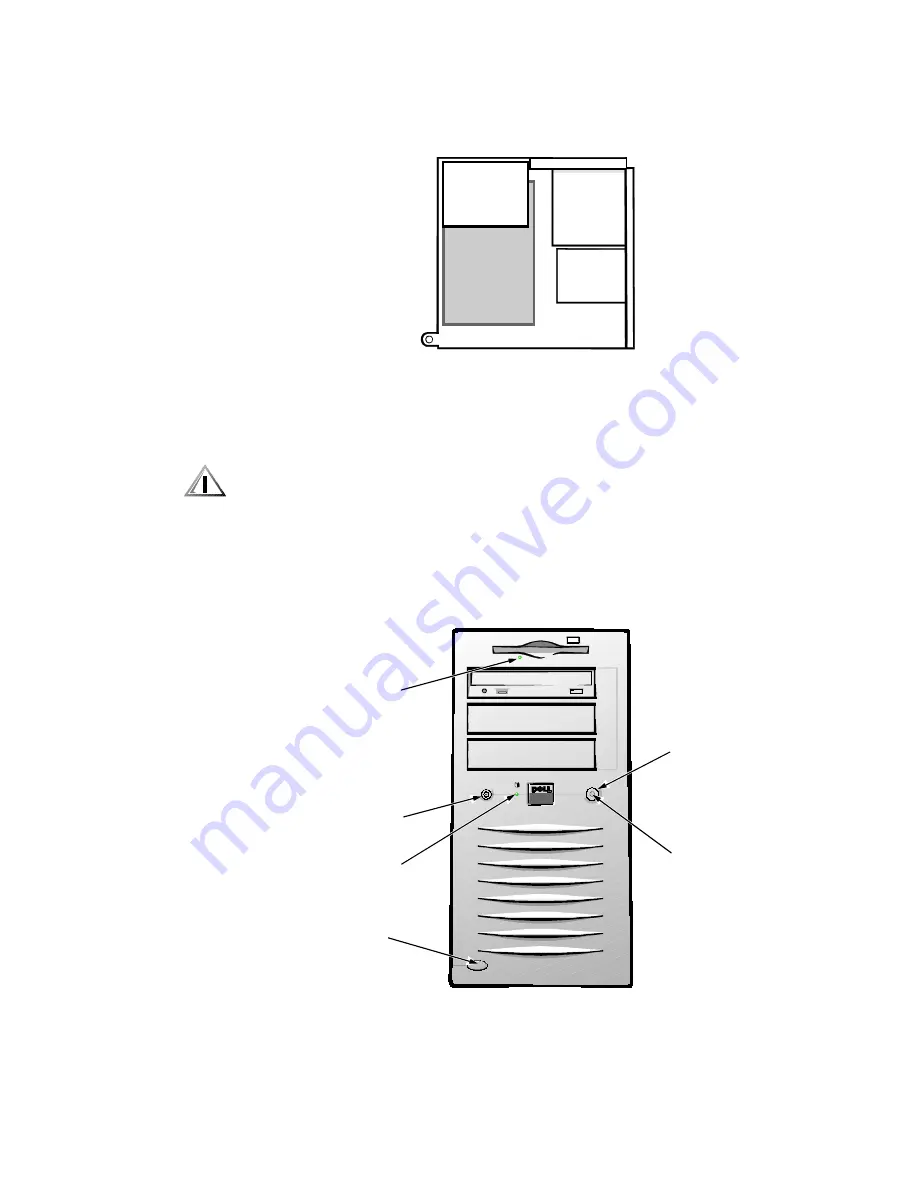
Figure 1-2 shows the location of some of the key front-panel features.
)LJXUH )URQW3DQHO )HDWXUHV
front
back
top
bottom
Mini Tower Computer
diskette-drive
access indicator
Mini Tower Computer
power indicator
hard-disk drive
access indicator
power button
reset button
computer cover
release button
Содержание Precision 610
Страница 1: ...ZZZ GHOO FRP HOO 3UHFLVLRQ RUN6WDWLRQ 0LQL 7RZHU 6 VWHPV 6 59 0 18 ...
Страница 2: ......
Страница 3: ...ZZZ GHOO FRP HOO 3UHFLVLRQ RUN6WDWLRQ 0LQL 7RZHU 6 VWHPV 6 59 0 18 ...
Страница 9: ...ix ...
Страница 34: ...1 24 Dell Precision 610 Mini Tower Systems Service Manual ...
Страница 42: ...2 8 Dell Precision 610 Mini Tower Systems Service Manual ...
Страница 54: ...3 12 Dell Precision 610 Mini Tower Systems Service Manual ...
Страница 88: ...A 6 Dell Precision 610 Mini Tower Systems Service Manual ...
Страница 93: ......
Страница 94: ... ZZZ GHOO FRP 3ULQWHG LQ WKH 8 6 3 1 ...