


Table 18. Ops panel LED states (continued)
LED
Status/description
Module
Fault
Amber indicates a fault in a controller module, IOM, PSU, or FCM. Check the drawer LEDs for indication of a
disk fault.
Logical
status
Amber indicates a fault from something other than firmware (usually a disk, an HBA, or an internal or external
RAID controller). Check the drawer LEDs for indication of a disk fault. See
Drawer 0
Fault
Amber indicates a disk, cable, or sideplane fault in drawer 0. Open the drawer and check DDICs for faults.
Drawer 1
Fault
Amber indicates a disk, cable, or sideplane fault in drawer 1. Open the drawer and check DDICs for faults.
CAUTION:
The sideplanes on the enclosure drawers are not hot swappable or customer serviceable.
ME5084 drawer LEDs
The following table describes the LEDs on the drawers:
Table 19. Drawer LED states
LED
Status/description
Sideplane
OK/Power
Good
Green if the sideplane is working and there are no power problems.
Drawer Fault Amber if a drawer component has failed. If the failed component is a disk, the LED on the failed DDIC will light
amber. Follow the procedure in
Replacing a DDIC in a 5U enclosure
on page 52. If the disks are OK, contact
your service provider to identify the cause of the failure, and resolve the problem.
CAUTION:
The sideplanes on the enclosure drawers are not hot swappable or customer
serviceable.
Logical Fault Amber (solid) indicates a disk fault. Amber (blinking) indicates that one or more storage systems are in an
impacted state.
Cable Fault
Amber indicates the cabling between the drawer and the back of the enclosure has failed. Contact your service
provider to resolve the problem.
Activity Bar
Graph
Displays the amount of data I/O from zero segments lit (no I/O) to all six segments lit (maximum I/O).
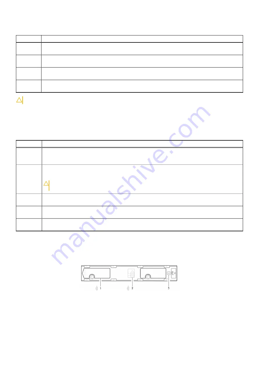
ME5084 DDIC LEDs
The DDIC supports LFF 3.5" and SFF 2.5" disks. The following figure shows the top panel of the DDIC as viewed when the disk
is aligned for insertion into a drawer slot.
Figure 39. LEDs: DDIC – 5U enclosure disk slot in drawer
1. Slide latch (slides left)
2. Latch button (shown in the locked position)
3. Drive Fault LED
36
Troubleshooting and problem solving


