background image

14

Dell PowerVault 2xxS Storage Systems SCSI Backplane Board Replacement Instructions

.

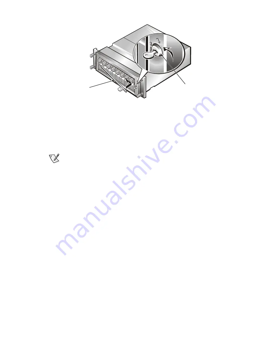
Figure 14.  Installing the Lock Bar (System Shown with a Removable 

Lock Bar)

5. Place the key in the keylock and turn it to the locked position. Remove the 

key from the keylock.

SCSI Backplane Board Replacement Completion

NOTE: For information on installation, cabling, and powering on the storage 
system, see the Dell PowerVault 200S, 201S, 210S, and 211S Storage Systems 
Installation and Service Guide.

After replacing the SCSI backplane board, complete the procedure by perform-
ing the following steps:

1.

Install the storage system in the rack from which it was removed. If the 
storage system was used in a stand-alone configuration, install the storage 
system in the stand-alone enclosure.

2. Connect the communication cable(s) coming from the host computer to 

the storage system.

3. Connect the power cable(s) from the storage system to the power 

source(s).

4. Turn on the storage system.

key lock

lock bar

Содержание PowerVault 200S

Страница 1: ...KING INSIDE THE STORAGE SYSTEM Before you start to work on the storage system perform the following steps in the sequence listed 1 Turn off the storage system 2 Disconnect the storage system from its power source s 3 Disconnect any communications cables 4 Wear a wrist grounding strap and clip it to an unpainted metal sur face such as a part of the chassis If a wrist grounding strap is not availabl...

Страница 2: ...s expander modules 12 Install the cooling fans 13 Install the power supplies 14 Install the hard disk drives Each procedure is described in the following sections Remove the SCSI Hard Disk Drives CAUTION Note the location of the SCSI hard disk drives as you remove them from the drive bays During the installation procedure found later in this document you must return the SCSI hard disk drives to th...

Страница 3: ...n the lock bar and gently pull it toward you about 1 2 inch away from the unlocked keylock b Slide the left end of the lock bar to the right to remove it from its hole see Figure 2 Figure 2 Keylock and Removable Lock Bar Black 3 Remove the hard disk drives NOTICE Handle the hard disk drives with care The carriers pro vide some protection but the hard disk drives can be damaged by rough handling Wh...

Страница 4: ...the power supply bays During the installation procedure found later in this document you must return the power supply and the power supply blank to the same power supply bays from which they were removed NOTE A redundant storage system has two power supplies A nonredundant storage system has one power supply and one power supply blank Because a power supply and a power supply blank are removed in ...

Страница 5: ...ove the remaining power supply Remove the Cooling Fans NOTICE In a nonredundant system note that the cooling fan blank is located in the right cooling fan bay During the installation proce dure found later in this document you must return the cooling fan blank to the right cooling fan bay NOTE A redundant storage system has three cooling fans A nonredundant storage system has two cooling fans and ...

Страница 6: ...erminator blank to the same module bays from which they were removed NOTICE In a redundant system note the location of the enclosure services or enclosure services expander modules as you remove them from the module bays During the installation procedure found later in this document you must return these modules to the same module bays from which they were removed NOTE A redundant storage system h...

Страница 7: ...dule bay see Figure 7 Figure 7 Enclosure Services Module Removal 3 Repeat steps 1 and 2 to remove the remaining enclosure services module Remove the Component Mounting Bracket To remove the component mounting bracket perform the following steps 1 Using a Phillips head screwdriver remove the two screws that secure the component mounting bracket to the chassis see Figure 8 2 Lift the component mount...

Страница 8: ... wiggle motion pull the module from the backplane board see Figure 9 Figure 9 Dual Bus Split Backplane Module Location Remove the SCSI Backplane Board To remove the SCSI backplane board perform the following steps 1 Looking in the rear of the storage system locate the fifteen screws that secure the two halves of the chassis together There are nine across the top and six across bottom of the backpl...

Страница 9: ...enclosure services module bays on the left and right side of the chassis see Figure 11 NOTE A magnetized 11 5 inch long 5 64 inch ball head driver is included with the SCSI backplane board in the service kit Figure 11 Screw Location in the Left Enclosure Services Module Bay 3 Separate the two chassis halves to remove the backplane board see Figure 12 Figure 12 Chassis Separation image shown withou...

Страница 10: ...f of the chassis Do not tighten the screws at this time NOTE If the front half of the chassis is slightly bowed down making it dif ficult to align the screw holes try installing a hard disk drive temporarily into one of the center drive bays The hard disk drive should straighten the bow in the chassis making it easier to thread the screws Remove the hard disk drive when all the screws are inserted...

Страница 11: ...the bottom of the housing goes into the slot on the center support of the component mounting bracket 3 Insert the two screws and using a Phillips head screwdriver tighten the screws to secure the component mounting bracket to the chassis Install the Enclosure Services Modules or Enclosure Services Expander Modules NOTICE In a nonredundant system install the enclosure services module or enclosure s...

Страница 12: ... into the empty cooling fan bay Push the cooling fan all the way to the back of the bay until it is seated in the connector 2 Using a Phillips head screwdriver turn the two captive screws clockwise until the cooling fan is secured to the cooling fan bay 3 Repeat steps 1 and 2 to install the remaining cooling fans Install the Power Supplies NOTICE In a nonredundant system install the power supply a...

Страница 13: ...arrier handle flips up Figure 13 Installing a SCSI Hard Disk Drive System Shown with a Swing out Lock Bar 2 Close the handle to draw the drive carrier into the bay and lock the drive in place 3 Repeat steps 1 and 2 to install the remaining hard disk drives 4 For a storage system with a silver swing out lock bar raise the lock bar to the lock position The lock bar slips down into a detent This hold...

Страница 14: ...e the Dell PowerVault 200S 201S 210S and 211S Storage Systems Installation and Service Guide After replacing the SCSI backplane board complete the procedure by perform ing the following steps 1 Install the storage system in the rack from which it was removed If the storage system was used in a stand alone configuration install the storage system in the stand alone enclosure 2 Connect the communica...

Отзывы: