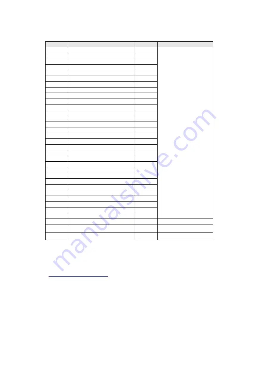
Dell P2422HB Скачать руководство пользователя страница 18

- 18 - 


No. 

Description 

Q’ty 

Remark 

TRIM 

For EMEA Only, not for 

other regions 

DECO PLATE tape 

DECO PLATE 

DECO PLATE sponge 

MIDDLE FRAME 

SIDE USB BOARD 

Screw Q3 

LENS 

LED BOARD 

10 

Screw Q2 

11 

BKT SPEAKER 

12 

PANEL 

13 

SCREW M3*3L 

13 

14 

SCREW M3*6L 

15 

SCREW M4 

16 

PWD MYLAR 

17 

POWER BOARD 

18 

MAINBOARD 

19 

MAINFRAME 

20 

QR-SLIDER 

21 

QR-BUTTON 

22 

SPRINGS 

23 

KEY BOARD 

24 

BUTTON  

25 

KEY 

26 

REAR COVER 

27 

DELL LOGO 

28 

SCREW M4*10L 

29 

Hinge ass’y 

30 

Base ass’y 

31 

Power Cable 

See “NOTE" 

32 

DP 1.2 cable 

See “NOTE" 

33 

USB 3.0 upstream  

See “NOTE" 


NOTE: 

For replacement of power cord, connectivity cable and external power supply (if applicable), 
contact Dell: 

1. Go to 

https:/www.dell.com/support


2. Verify your country or region in the Choose A Country/Region drop-down menu at the bottom-

right corner of the page. 

3. Click Contact Us next to the country dropdown. 

4. Select the appropriate service or support link based on your need. 

5. Choose the method of contacting Dell that is convenient for you 

Содержание P2422HB

Страница 1: ... 1 Service Manual P2422Hb P2422Hc Version 01 Date 2022 03 11 ...

Страница 2: ...Hb 9 5 Disassembly and Assembly Procedures P2422Hb 10 5 1 Disassembly SOP P2422Hb 10 5 2 Assembly SOP P2422Hb 14 6 Exploded view diagram with list of items P2422Hc 17 7 Wiring connectivity diagram P2422Hc 19 8 Disassembly and Assembly Procedures P2422Hc 20 8 1 Disassembly Procedures P2422Hc 20 8 2 Assembly Procedures P2422Hc 25 9 How to connect and disconnect power cable connectivity cable 27 10 T...

Страница 3: ...or place equipment so close together that it is subject to recalculated or preheated air NOTE Review the weight limits referenced in your computer documentation before placing a monitor or other devices on top of your computer Ensure that nothing rests on your equipment s cables and that the cables are not located where they can be stepped on or tripped over Ensure that all cables are connected to...

Страница 4: ...omponents inside your equipment Under certain conditions ESD may build up on your body or an object such as a peripheral and then discharge into another object such as your computer To prevent ESD damage you should discharge static electricity from your body before you interact with any of your equipment s internal electronic components such as a memory module You can protect against ESD by touchi...

Страница 5: ...as risk of electric shock and or fire Ensure that the ground prong of the power plug is inserted into the mating ground contact of the power strip Be sure to grasp the plug not the cable when disconnecting equipment from an electric socket If your equipment uses an AC adapter Use only the Dell provided AC adapter approved for use with this device Use of another AC adapter may cause a fire or explo...

Страница 6: ... 6 2 Check Label behind monitor 2 1 P2422Hb Please follow Instruction for P2422Hb 2 2 P2422Hc Please follow instruction for P2422Hc start from section 6 P2422Hb P2422Hc ...

Страница 7: ...CBA USB BD 1 5 MYLAR PWR BD 1 6 PCBA SPS BD 1 7 PCBA I F BD 1 8 ASSY SHD SGCC 0 5T P2222HB 1 9 PCBA CTRL BD 1 10 ASSY RC 1 11 ASSY STAND CLMN 1 12 ASSY STAND BASE 1 13 Power cable 1 See NOTE 14 DisplayPort 1 2 cable 1 See NOTE 15 VGA cable 1 See NOTE 16 HDMI 1 4 cable 1 See NOTE 17 USB 3 0 upstream cable 1 See NOTE 15 16 17 1 2 4 5 6 3 8 7 9 10 11 12 14 13 4 ...

Страница 8: ...ps www dell com support 2 Verify your country or region in the Choose A Country Region drop down menu at the bottom right corner of the page 3 Click Contact Us next to the country dropdown 4 Select the appropriate service or support link based on your need 5 Choose the method of contacting Dell that is convenient for you ...

Страница 9: ... 9 4 Wiring connectivity diagram P2422Hb Wire1 FFC 1 FFC 2 ...

Страница 10: ...nt equipment materials as bellow 1 Working table 2 Philips head screwdriver 3 Hex head screwdriver 4 Gloves 5 Cleaning cloth 6 ESD protection Item Picture Operation Tool Notes 1 To remove the stand 1 Place the monitor on a soft cloth or cushion at the edge of the desk 2 Press and hold the stand release button at the back of the display 3 Lift the stand assembly up and away from the monitor 2 1 Unl...

Страница 11: ...to take off Rear Cover 4 1 Pull out USB FFC from I F BD 5 Other Panel LGD Panel 1 Tear off adhesive tape on Backlight Wire 2 Tear off adhesive tape on LVDS Cable Note Only for LG panel 3 Tear off two tapes to disassemble Main SHD from panel ...

Страница 12: ...BD 2 Pull out LVDS cable and take off Main SHD from panel 7 1 Disassemble Mylar from Main SHD 2 Unlock 5 PCB screws and 2 hex screws 1 Philips head screwdriver Torsion of PCB screw 8 5 1kgf 2 Hex head screwdriver Torsion of hex screw 5 0 6Kgf ...

Страница 13: ... 13 8 1 Take out I F BD and SPS BD from Main SHD 2 Pull out LVDS cable and SPS BD cable from I F BD ...

Страница 14: ...er 4 Gloves 5 Cleaning cloth 6 ESD protection Item Picture Operation Tools Notes 1 1 Assemble SPS BD in Main SHD 2 Insert the LVDS cable into I F BD 3 Insert SPS BD cable into I F BD and then assemble I F BD into Main SHD 4 Lock 5 PCB screws and 2 hex screws 1 Philips head screwdriver Torsion of PCB screw 8 5 1kgf 2 Hex head screwdriver Torsion of hex screw 5 0 6Kgf 2 1 Assemble Mylar Paste Mylar ...

Страница 15: ... into Panel 2 Paste acetate tape to fix LVDS cable on panel Note Only for LG panel 3 Insert Backlight Wire into SPS BD and paste 1 tape to fix wire 4 1 Place Main SHD on panel and paste 2 tapes to fix Main SHD 5 1 Insert USB FFC to USB BD and I F BD ...

Страница 16: ...Assemble Stand a Insert the stand base blocks fully into the stand slot b Lift the screw handle and turn the screw clockwise c After fully tightening the screw fold the screw handle flat within the recess 8 1 Attach the stand assembly to the display a Fit the two tabs on the upper part of the stand to the groove on the back of the display b Press the stand down till it snaps into place 4 1 1 2 3 3...

Страница 17: ... 17 6 Exploded view diagram with list of items P2422Hc 31 32 33 ...

Страница 18: ...TTON 2 25 KEY 1 26 REAR COVER 1 27 DELL LOGO 1 28 SCREW M4 10L 4 29 Hinge ass y 1 30 Base ass y 1 31 Power Cable 1 See NOTE 32 DP 1 2 cable 1 See NOTE 33 USB 3 0 upstream 1 See NOTE NOTE For replacement of power cord connectivity cable and external power supply if applicable contact Dell 1 Go to https www dell com support 2 Verify your country or region in the Choose A Country Region drop down men...

Страница 19: ... 19 7 Wiring connectivity diagram P2422Hc ...

Страница 20: ...the tools that would typically can be used to disassemble the product to a point where components and materials requiring selective treatment can be removed Tool Description Screwdriver Phillip head Hexagonal head Penknife 8 1 Disassembly Procedures P2422Hc Step Figure Tool Remark Remove the Base ass y Push the button and pull out the stand Note Put the monitor on a flat soft and clean surface Uns...

Страница 21: ... 21 Remove the Rear cover Take scraper insert the bezel bottom site Disconnect the FFC cables and LVDS cable Remove the connectors and tapes ...

Страница 22: ...move the mainframe Tear out all the tapes Unscrew the 2 screws on the USB board and mainframe Torque 6 1kgf cm Tear out the wires and mylar remove the screws on the board by the Philips head Torque 6 1kgf cm ...

Страница 23: ... 23 Remove the mainboard and power board Unscrew the plastic screws on the mylar Mainboard and power board ...

Страница 24: ... 24 Remove the middle frame Unscrew the screws on the middle frame panel ...

Страница 25: ...Procedures P2422Hc Step Figure Tool Remark Assemble the middle frame screw the screws on the middle frame Assemble the maylar push the screws by hand Assemble mainboard and power board Tighten the screws on the board t ...

Страница 26: ... the FFC cables and LVDS cable Connect all connectors and tapes Tighten the screw on the board Assemble the rear cover Tighten the 4 screws by the Philips head Screwdriver Torque 6 1kgf cm Assemble the stand ass y ...

Страница 27: ...able connectivity cable WARNING To change power cable connectivity cable switch off power before unplugging the cable and replugging in required cable Connecting disconnecting Power cable Connect disconnecting the DisplayPort cable and USB cable ...

Страница 28: ... 28 Connecting disconnecting the HDMI cable optional Connecting disconnecting the VGA cable optional ...

Страница 29: ... 29 10 Trouble shooting instructions ...

Страница 30: ... 30 ...

Страница 31: ... 31 ...

Страница 32: ... 32 ...

Страница 33: ... 33 ...

Страница 34: ... 34 ...

Страница 35: ... 35 ...

Страница 36: ... 36 ...

Страница 37: ... 37 ...

Отзывы: