


3.
Disconnect the following from the system board:
a. camera cable
b. LVDS cable
c. system-fan cable
d. optical-drive cable
e. hard-drive cable
f. hard-drive/optical-drive power cable
g. convertor-board cable
h. power-switch cable
i. touch cable (if available)
j. speaker cable
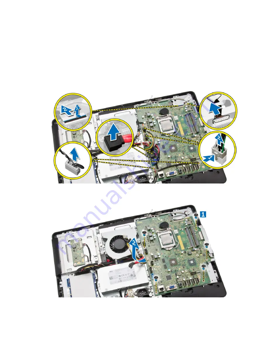
4.
Perform the following steps as shown in the illustration:
a. Remove the screws that secure the system board to the computer [1].
b. Slide the system board to release it from the computer [2].
26


