Dell Latitude X300 Скачать руководство пользователя страница 25

Memory, Modem, and Mini PCI Card Modules: Dell Latitude X300 Service Manual 


1

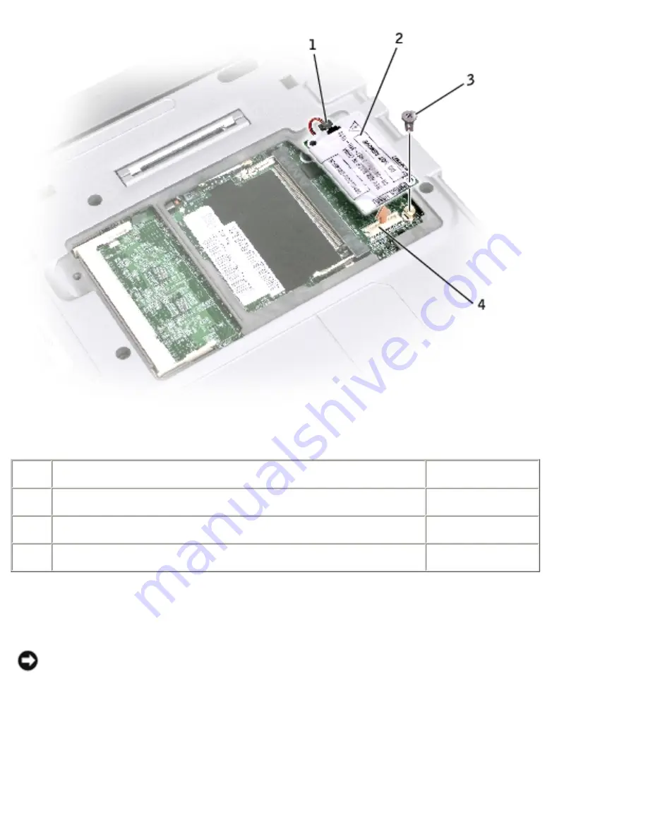
modem cable connector


2

modem

Y0231

3

modem screw


4

system board connector


10.  Connect the modem cable to the modem. 

NOTICE: 

The connectors are keyed to ensure correct insertion. If you feel 

resistance, check the connectors and realign the card. 

11.  Align the modem with the screw hole and press the modem into the connector 

on the system board. 

12.  Install the screw to secure the modem to the system board. 

file:///F|/Service%20Manuals/Dell/Latitude/x300/upgrades.htm (8 of 14) [2/28/2004 8:26:29 AM]

Содержание Latitude X300

Страница 1: ...he BIOS Pin Assignments for I O Connectors Mini Recommended Spares List Notes Notices and Cautions NOTE A NOTE indicates important information that helps you make better use of your computer NOTICE A NOTICE indicates either potential damage to hardware or loss of data and tells you how to avoid the problem CAUTION A CAUTION indicates a potential for property damage personal injury or death Informa...

Страница 2: ...less otherwise noted each procedure assumes that the following conditions exist You have performed the steps in Shutting Down Your Computer You have read the safety information in your System Information Guide Recommended Tools The procedures in this document may require the following tools Small flat blade screwdriver Phillips screwdriver Small plastic scribe Flash BIOS update program floppy disk...

Страница 3: ...s in on the locking tabs before you disconnect the cable As you pull connectors apart keep them evenly aligned to avoid bending any connector pins Also before you connect a cable ensure that both connectors are correctly oriented and aligned NOTICE To avoid damaging the computer perform the following steps before you begin working inside the computer 1 Ensure that the work surface is flat and clea...

Страница 4: ...e any installed PC Cards from the PC Card slot 8 Remove any installed Secure Digital memory card from the Secure Digital memory slot 9 Close the display and turn the computer upside down on a flat work surface NOTICE To avoid damaging the system board you must remove the main battery before you service the computer 10 Slide and hold the battery bay latch release on the bottom of the computer and t...

Страница 5: ...tery latch release 2 G0767 11 Remove any installed modules including a second battery if installed 12 Remove the hard drive Computer Orientation 1 front 2 left 3 back 4 right file F Service 20Manuals Dell Latitude x300 before htm 4 of 7 2 28 2004 8 26 24 AM ...

Страница 6: ...o lay out and keep track of the screws The placemat provides the number of screws and their sizes NOTICE When reinstalling a screw you must use a screw of the correct diameter and length Ensure that the screw is properly aligned with its corresponding hole and avoid overtightening file F Service 20Manuals Dell Latitude x300 before htm 5 of 7 2 28 2004 8 26 24 AM ...

Страница 7: ...titude X300 Service Manual Keyboard 4 each Palm Rest 9 each Display Assembly 2 each Keyboard Tray 5 each Hard Drive 4 each System Board 3 each file F Service 20Manuals Dell Latitude x300 before htm 6 of 7 2 28 2004 8 26 24 AM ...

Страница 8: ...n Dell Latitude X300 Service Manual Modem Card 1 each Cooling Fan 4 each Speakers 1 each Bluetooth Module 1 each Back to Contents Page file F Service 20Manuals Dell Latitude x300 before htm 7 of 7 2 28 2004 8 26 24 AM ...

Страница 9: ...elp you resolve the problem without contacting Dell If you do contact Dell the test results can provide important information for Dell s service and support personnel The Dell Diagnostics allows you to Perform tests on one or all devices Select tests based on a symptom of the problem you are having Choose how many times a test is run Suspend testing if an error is detected Access help information ...

Страница 10: ...n the mute button and press the computer s power button to begin the Dell Diagnostics The computer automatically runs the Pre boot System Assessment NOTE If you see a message stating that no diagnostics utility partition has been found run the Dell Diagnostics from your Drivers and Utilities CD If you wait too long and the Microsoft Windows logo appears continue to wait until you see the Windows d...

Страница 11: ...on Express Test Performs a quick test of devices This test typically takes 10 to 20 minutes and requires no interaction on your part Run Express Test first to increase the possibility of tracing the problem quickly Extended Test Performs a thorough check of devices This test typically takes an hour or more and requires you to answer questions periodically Custom Test Tests a specific device You ca...

Страница 12: ...requirements for running the test Configuration Displays your hardware configuration for the selected device The Dell Diagnostics obtains configuration information for all devices from the system setup program memory and various internal tests and it displays the information in the device list in the left pane of the screen The device list may not display the names of all the components installed ...

Страница 13: ...ician should perform repairs on your computer Damage due to servicing that is not authorized by Dell is not covered by your warranty NOTICE Unless otherwise noted each procedure in this manual assumes that a part can be replaced by performing the removal procedure in reverse order file F Service 20Manuals Dell Latitude x300 system htm 1 of 2 2 28 2004 8 26 26 AM ...

Страница 14: ...rve battery W2662 3 keyboard tray 10 Bluetooth module 2U381 4 battery M0270 11 system board see Mini RSL 5 cooling fan D2589 12 palm rest G0808 6 hard drive see Mini RSL 13 keyboard 5Y730 7 bottom case see Mini RSL Back to Contents Page file F Service 20Manuals Dell Latitude x300 system htm 2 of 2 2 28 2004 8 26 26 AM ...

Страница 15: ...hoose to replace the battery with the computer in standby mode you have up to 1 minute to complete the battery replacement The computer will shut down shortly after this 1 Ensure that the computer is turned off suspended in a power management mode or connected to an electrical outlet 2 If the computer is connected to a media base docked undock it See the documentation that came with your media bas...

Страница 16: ...ery latch release 2 G0767 Installing the Battery To install the battery slide the battery or the optional extended battery into the bay until the latch release clicks file F Service 20Manuals Dell Latitude x300 battery htm 2 of 3 2 28 2004 8 26 26 AM ...

Страница 17: ...Battery Dell Latitude X300 Service Manual 1 optional extended battery Y0037 Back to Contents Page file F Service 20Manuals Dell Latitude x300 battery htm 3 of 3 2 28 2004 8 26 26 AM ...

Страница 18: ...urchased from Dell are covered under your computer warranty CAUTION Before you begin any of the procedures in this section follow the safety instructions in the System Information Guide 1 Ensure that the work surface is flat and clean to prevent scratching the computer cover 2 Save and close any open files exit any open programs and shut down the computer 3 If the computer is connected to the medi...

Страница 19: ...er Continue to ground yourself periodically during this procedure 7 Turn the computer over unscrew both captive screw s from the memory module Mini PCI modem cover and remove the cover 1 captive screw 2 2 memory module cover H0164 NOTICE To prevent damage to the memory module connector do not use tools to spread the memory module securing clips file F Service 20Manuals Dell Latitude x300 upgrades ...

Страница 20: ...ourself by touching a metal connector on the back of the computer Continue to ground yourself periodically during this procedure a Use your fingertips to carefully spread apart the securing clips on each end of the memory module connector until the module pops up b Remove the module from the connector 1 memory module see Mini RSL 2 securing clips 2 file F Service 20Manuals Dell Latitude x300 upgra...

Страница 21: ...ule firmly into the slot at a 45 degree angle and rotate the module down until it clicks into place If you do not hear the click remove the module and reinstall it NOTE If the memory module is not installed properly the computer may not boot properly No error message indicates this failure 1 memory module see Mini RSL 2 connector 10 Replace the cover file F Service 20Manuals Dell Latitude x300 upg...

Страница 22: ... computer 1 captive screw 2 2 memory module cover H0164 11 Insert the battery into the battery bay or connect the AC adapter to your computer and an electrical outlet 12 Turn on the computer As the computer boots it detects the additional memory and automatically updates the system configuration information file F Service 20Manuals Dell Latitude x300 upgrades htm 5 of 14 2 28 2004 8 26 29 AM ...

Страница 23: ...2 Save and close any open files exit any open programs and then shut down the computer 3 If the computer is connected to a media base docked undock it See the documentation that came with the media base for instructions 4 Disconnect the computer from the electrical outlet 5 Wait 10 to 20 seconds and then disconnect any attached devices 6 Remove any installed PC Cards or blanks battery and devices ...

Страница 24: ... 9 If you are replacing a modem remove the existing modem a Remove the screw securing the modem to the system board and set it aside b Pull straight up on the attached pull tab to lift the modem out of its connector on the system board and disconnect the modem cable file F Service 20Manuals Dell Latitude x300 upgrades htm 7 of 14 2 28 2004 8 26 29 AM ...

Страница 25: ... the modem NOTICE The connectors are keyed to ensure correct insertion If you feel resistance check the connectors and realign the card 11 Align the modem with the screw hole and press the modem into the connector on the system board 12 Install the screw to secure the modem to the system board file F Service 20Manuals Dell Latitude x300 upgrades htm 8 of 14 2 28 2004 8 26 29 AM ...

Страница 26: ...uter is connected to a media base docked undock it See the documentation that came with the media base for instructions 4 Disconnect the computer from the electrical outlet 5 Wait 10 to 20 seconds and then disconnect any attached devices 6 Remove any installed PC Card or blanks battery and devices NOTICE Handle modules and cards by their edges and avoid touching pins and contacts Ground yourself b...

Страница 27: ... screw 2 2 cover 8 If a Mini PCI card is not already installed go to step 10 9 If you are replacing a Mini PCI card remove the existing card a Disconnect the Mini PCI card from the attached cables file F Service 20Manuals Dell Latitude x300 upgrades htm 10 of 14 2 28 2004 8 26 29 AM ...

Страница 28: ...s Dell Latitude X300 Service Manual 1 cable connectors b Release the Mini PCI card by spreading the metal securing tabs until the card pops up slightly file F Service 20Manuals Dell Latitude x300 upgrades htm 11 of 14 2 28 2004 8 26 29 AM ...

Страница 29: ...p of or under the card 10 To replace a Mini PCI card align the card with the connector at a 45 degree angle and press the Mini PCI card into the connector 11 Lower the Mini PCI card toward the inner tabs to approximately a 20 degree angle 12 Continue lowering the Mini PCI card until it snaps into the inner tabs of the connector file F Service 20Manuals Dell Latitude x300 upgrades htm 12 of 14 2 28...

Страница 30: ...CI card N0498 13 Connect the antenna cable to the antenna connector on the Mini PCI card NOTICE The connectors are keyed for correct insertion If you feel resistance check the connectors and realign the card file F Service 20Manuals Dell Latitude x300 upgrades htm 13 of 14 2 28 2004 8 26 29 AM ...

Страница 31: ... PCI Card Modules Dell Latitude X300 Service Manual 1 cable connector 14 Replace the cover and tighten the screws Back to Contents Page file F Service 20Manuals Dell Latitude x300 upgrades htm 14 of 14 2 28 2004 8 26 29 AM ...

Страница 32: ...ormation Guide NOTICE Disconnect the computer and any attached devices from electrical outlets NOTICE To avoid ESD ground yourself by using a wrist grounding strap or by touching an unpainted metal surface on the computer NOTICE Read Before You Begin before performing the following procedure 1 Remove the battery 2 Remove the four M2 x 4 mm screws labeled with an arrow from the bottom of the comput...

Страница 33: ...fragile easily dislodged and time consuming to replace Be careful when removing and handling the keyboard 3 Turn the computer over and insert a inch flat blade screwdriver into the slot to the right of the keyboard locator tab file F Service 20Manuals Dell Latitude x300 keyboard htm 2 of 6 2 28 2004 8 26 30 AM ...

Страница 34: ...e the four securing tabs located across the back edge of the keyboard 6 Rotate the keyboard toward the front of the computer and place it face down on the palm rest NOTICE Do not pull on the keyboard flex cable 7 Open the ZIF connector on the system board by pulling the ZIF connector tabs toward the back of the computer file F Service 20Manuals Dell Latitude x300 keyboard htm 3 of 6 2 28 2004 8 26...

Страница 35: ...or 2 keyboard flex cable 3 ZIF connector tabs 2 8 Remove the keyboard flex cable from the ZIF connector 9 Lift the keyboard up and out of the computer Replacing the Keyboard file F Service 20Manuals Dell Latitude x300 keyboard htm 4 of 6 2 28 2004 8 26 30 AM ...

Страница 36: ...nnector until the line disappears and hold the cable steady while you close the ZIF connector The white line may reappear after the connector is closed which should not indicate a problem with the connection NOTICE Position the keyboard flex cable so that it is not pinched when you replace the keyboard in the bottom case 5 Rotate the keyboard back and fit it into the bottom case 6 Ensure that all ...

Страница 37: ...Keyboard Dell Latitude X300 Service Manual file F Service 20Manuals Dell Latitude x300 keyboard htm 6 of 6 2 28 2004 8 26 30 AM ...

Страница 38: ...ide NOTICE Disconnect the computer and any attached devices from electrical outlets NOTICE To avoid ESD ground yourself by using a wrist grounding strap or by touching an unpainted metal surface on the computer NOTICE Read Before You Begin before performing the following procedure 1 Remove the battery 2 Remove the keyboard 3 Turn the computer over and remove the three M2 x 4 mm screws from the bot...

Страница 39: ...300 Service Manual 1 M2 x 4 mm screws 3 98MKC 4 Turn the computer over and open the display 5 Remove the six M2 x 4 mm screws on the palm rest file F Service 20Manuals Dell Latitude x300 palmrest htm 2 of 5 2 28 2004 8 26 31 AM ...

Страница 40: ... mm screws 6 98MKC 6 Lift up and rotate the palm rest forward 7 Lift the ZIF connector and disconnect the palm rest flex cable from its ZIF connector on the system board file F Service 20Manuals Dell Latitude x300 palmrest htm 3 of 5 2 28 2004 8 26 31 AM ...

Страница 41: ...e connection a locator line has been added near the end of the palm rest flex cable When replacing the palm rest flex cable press the cable into the connector until the line aligns with the system board and hold it steady while you snap the ZIF connector down The locator line may reappear after the connector is file F Service 20Manuals Dell Latitude x300 palmrest htm 4 of 5 2 28 2004 8 26 31 AM ...

Страница 42: ...est Dell Latitude X300 Service Manual closed which should not indicate a problem with the connection Back to Contents Page file F Service 20Manuals Dell Latitude x300 palmrest htm 5 of 5 2 28 2004 8 26 31 AM ...

Страница 43: ...ices from electrical outlets NOTICE To avoid ESD ground yourself by using a wrist grounding strap or by touching an unpainted metal surface on the computer NOTICE Read Before You Begin before performing the following procedure 1 Remove the battery 2 Remove the keyboard 3 Remove the palm rest 4 Loosen the four M2 x 5 5 mm screws that secure the hard drive to the bottom case Rubber grommets secure e...

Страница 44: ... hard drive see Mini RSL 3 M2 x 5 5 mm screws 4 6K709 5 Disconnect the hard drive connector from the system board 6 Lift the hard drive up and out of the bottom case Replacing the Hard Drive file F Service 20Manuals Dell Latitude x300 hdd htm 2 of 3 2 28 2004 8 26 32 AM ...

Страница 45: ...e system board 2 Position the hard drive on the bottom case and tighten the four M2 x 5 5 mm screws to the bottom case NOTE The rubber grommets help you avoid overtightening the screws Back to Contents Page file F Service 20Manuals Dell Latitude x300 hdd htm 3 of 3 2 28 2004 8 26 32 AM ...

Страница 46: ...embly Hinge Covers Removing the Hinge Covers CAUTION Before you begin any of the procedures in this section follow the safety instructions in the System Information Guide 1 Remove the battery 2 On the inside of the battery bay use your fingers to unhook the hinge covers from the back of the computer file F Service 20Manuals Dell Latitude x300 display htm 1 of 7 2 28 2004 8 26 33 AM ...

Страница 47: ...ll the way 180 degrees so that it lies flat against your work surface 2 Place the hinge covers over the display hinges a The left hinge cover fits over the power button Both hinge covers pass through the display hinges to the back of the computer b Ensure that the two securing tabs on the outer edge of each hinge cover are engaged in their respective slots file F Service 20Manuals Dell Latitude x3...

Страница 48: ...in any of the procedures in this section follow the safety instructions in the System Information Guide NOTICE Disconnect the computer and any attached devices from electrical outlets NOTICE To avoid ESD ground yourself by using a wrist grounding strap or by touching an unpainted metal surface on the computer NOTICE Read Before You Begin before performing the following procedure 1 Remove the batte...

Страница 49: ...Display Assembly Dell Latitude X300 Service Manual 1 M3 x 5 mm screws 2 7T775 4 Turn the computer over and open the display 180 degrees file F Service 20Manuals Dell Latitude x300 display htm 4 of 7 2 28 2004 8 26 33 AM ...

Страница 50: ...uter 6 Disconnect both the antenna connectors NOTICE Do not pull on the signal cable Pull the signal connector to disconnect the cables 7 Disconnect the signal cable from the system board 8 If a tape secures the signal connector remove it and disconnect the signal cable from the system board file F Service 20Manuals Dell Latitude x300 display htm 5 of 7 2 28 2004 8 26 33 AM ...

Страница 51: ...Remove the display assembly out of the bottom case Replacing the Display 1 Replace the display assembly into the bottom case and open the display 180 degrees 2 Replace the two M2 x 6 mm screws by the display hinges on the top of the computer file F Service 20Manuals Dell Latitude x300 display htm 6 of 7 2 28 2004 8 26 33 AM ...

Страница 52: ... board 5 If a tape secured the signal connector replace it and connect the signal cable to the system board 6 Close the display and turn the computer over 7 Replace the two M3 x 5 mm screws from the bottom of the computer 8 Replace the keyboard 9 Replace the battery Back to Contents Page file F Service 20Manuals Dell Latitude x300 display htm 7 of 7 2 28 2004 8 26 33 AM ...

Страница 53: ... devices from electrical outlets NOTICE To avoid ESD ground yourself by using a wrist grounding strap or by touching an unpainted metal surface on the computer NOTICE Read Before You Begin before performing the following procedure 1 Remove the battery 2 Remove the keyboard 3 Remove the palm rest 4 Remove the hinge covers 5 Remove the display assembly 6 Remove the five M2 x 4 mm screws that secure ...

Страница 54: ...yboard tray up and slip out the antenna cables before lifting the tray out of the bottom case Replacing the Keyboard Tray 1 Replace the keyboard tray 2 Route the antenna cables through the oval opening on the keyboard tray file F Service 20Manuals Dell Latitude x300 keytray htm 2 of 3 2 28 2004 8 26 34 AM ...

Страница 55: ... antenna cable connectors 2 oval opening on keyboard tray 3 Reinstall the five M2 x 4 mm screws that secure the keyboard tray to the system board Back to Contents Page file F Service 20Manuals Dell Latitude x300 keytray htm 3 of 3 2 28 2004 8 26 34 AM ...

Страница 56: ...y attached devices from electrical outlets NOTICE To avoid ESD ground yourself by using a wrist grounding strap or by touching an unpainted metal surface on the computer NOTICE Read Before You Begin before performing the following procedure 1 Remove the battery 2 Remove the keyboard 3 Remove the palm rest NOTICE Do not pull on the reserve battery cable Pull from the reserve battery connector to di...

Страница 57: ...tem board connector 5 Disconnect the speaker cables 6 Pry the reserve battery free from the bottom case The reserve battery is attached to the bottom case with a piece of adhesive tape 7 Remove any remnants of the adhesive tape from the bottom case file F Service 20Manuals Dell Latitude x300 rsrvbatt htm 2 of 4 2 28 2004 8 26 35 AM ...

Страница 58: ...nnector to the system board connector 2 Press the reserve battery into place on the bottom case 3 Ensure that the cable is routed correctly as shown to avoid damaging the cable 1 reserve battery cable 4 Connect the speaker cables file F Service 20Manuals Dell Latitude x300 rsrvbatt htm 3 of 4 2 28 2004 8 26 35 AM ...

Страница 59: ...tery Dell Latitude X300 Service Manual 1 speaker cables 2 speakers see Mini RSL 5 Update the CMOS settings Back to Contents Page file F Service 20Manuals Dell Latitude x300 rsrvbatt htm 4 of 4 2 28 2004 8 26 35 AM ...

Страница 60: ...devices from electrical outlets NOTICE To avoid ESD ground yourself by using a wrist grounding strap or by touching an unpainted metal surface on the computer NOTICE Read Before You Begin before performing the following procedure 1 Remove the battery 2 Remove the keyboard 3 Remove the palm rest 4 Remove the M2 x 4 mm screw that secures the speaker to the bottom case NOTE The left and right speaker...

Страница 61: ...s 2 see Mini RSL NOTICE Do not pull on the speaker cable Pull from the speaker connector to disconnect the cable 5 Disconnect the speaker cable from the system board connector NOTICE Handle the speakers with care to avoid damaging them 6 Remove the speaker by pulling it straight up and out of the bottom case file F Service 20Manuals Dell Latitude x300 speakers htm 2 of 3 2 28 2004 8 26 35 AM ...

Страница 62: ...Speakers Dell Latitude X300 Service Manual Back to Contents Page file F Service 20Manuals Dell Latitude x300 speakers htm 3 of 3 2 28 2004 8 26 35 AM ...

Страница 63: ...ng the Bluetooth Module CAUTION Before you begin any of the procedures in this section follow the safety instructions in the System Information Guide 1 Remove the M2 x 5 mm screw 2 Disconnect the cable from the system board 3 Lift the assembly out file F Service 20Manuals Dell Latitude x300 bluetoot htm 1 of 3 2 28 2004 8 26 36 AM ...

Страница 64: ...uetooth module 2U381 3 Bluetooth module cable 4 connector on system board 4 To replace the Bluetooth module a Replace the assembly b Connect the cable to the system board c Replace the screw file F Service 20Manuals Dell Latitude x300 bluetoot htm 2 of 3 2 28 2004 8 26 36 AM ...

Страница 65: ...Bluetooth Module Dell Latitude X300 Service Manual Back to Contents Page file F Service 20Manuals Dell Latitude x300 bluetoot htm 3 of 3 2 28 2004 8 26 36 AM ...

Страница 66: ...e computer and any attached devices from electrical outlets NOTICE To avoid ESD ground yourself by using a wrist grounding strap or by touching an unpainted metal surface on the computer NOTICE Read Before You Begin before performing the following procedure 1 Remove the battery 2 Remove the keyboard 3 Remove the palm rest 4 Remove the four M2 x 3 mm screws that secure the cooling fan to the system...

Страница 67: ...an cable 4 cooling fan connector 5 system board connector 5 Remove the tape that secures the cooling fan cable to the fan NOTICE Do not pull on the cooling fan cable Pull from the cooling fan connector to disconnect the cable file F Service 20Manuals Dell Latitude x300 fan htm 2 of 3 2 28 2004 8 26 37 AM ...

Страница 68: ...rvice Manual 6 Disconnect the cooling fan cable from the system board connector 7 Lift the cooling fan up and out of the bottom case Back to Contents Page file F Service 20Manuals Dell Latitude x300 fan htm 3 of 3 2 28 2004 8 26 37 AM ...

Страница 69: ...and any attached devices from electrical outlets NOTICE To avoid ESD ground yourself by using a wrist grounding strap or by touching an unpainted metal surface on the computer NOTICE Read Before You Begin before performing the following procedure 1 Remove the battery 2 Remove the keyboard 3 Remove the palm rest 4 Remove the hinge covers 5 Remove the display assembly 6 Remove the keyboard tray 7 Re...

Страница 70: ... inside of the bottom case use your fingers to unhook the latch from the bottom case and the snap tabs catching the latch button on the outside of the bottom case 1 spring 2 battery lock latch G0767 3 bottom case 4 battery lock latch G0767 file F Service 20Manuals Dell Latitude x300 batlatch htm 2 of 3 2 28 2004 8 26 38 AM ...

Страница 71: ...the bottom case making certain that the snap tabs are fully engaged in the latch NOTE The battery latch release has springs and should be installed on the bottom case 2 Ensure that the newly installed latch moves smoothly and freely when pushed and released Back to Contents Page file F Service 20Manuals Dell Latitude x300 batlatch htm 3 of 3 2 28 2004 8 26 38 AM ...

Страница 72: ...attached devices from electrical outlets NOTICE To avoid ESD ground yourself by using a wrist grounding strap or by touching an unpainted metal surface on the computer NOTICE Read Before You Begin before performing the following procedure 1 Remove the battery 2 Remove the keyboard 3 Remove the palm rest 4 Remove the hinge covers 5 Remove the display assembly 6 Remove the keyboard tray 7 Remove the...

Страница 73: ...e the three M2 x 4 mm screws that secure the system board to the bottom case NOTE Each system board screw has an arrow beside it 1 system board see Mini RSL 2 M2 x 4 mm screws 3 98MKC 3 status light LED cable file F Service 20Manuals Dell Latitude x300 sysboard htm 2 of 4 2 28 2004 8 26 39 AM ...

Страница 74: ...a Bluetooth device is present 15 Lift the ZIF connector and remove the status light LED cable from its ZIF connector on the system board 16 Lift the system board up from the right side and out of the bottom case Replacing the System Board 1 Place the system board in the bottom case NOTE Route cables so that they will not be crimped or pinched when the complete assembly is put back together file F ...

Страница 75: ...connectors 3 Reinstall the three M2 x 4 mm screws that secure the system board to the bottom case NOTE After replacing the system board enter the computer Service Tag into the BIOS of the replacement system board Back to Contents Page file F Service 20Manuals Dell Latitude x300 sysboard htm 4 of 4 2 28 2004 8 26 39 AM ...

Страница 76: ...e the one time registration 2 Enter the Service Tag for your computer or select the appropriate Dell computer Click Go 3 Click Downloads 4 Select the appropriate operating system and language for your computer 5 Select the FlashBIOS Updates download category Click Go 6 Click the BIOS link and follow the instructions to download the BIOS to your computer Back to Contents Page file F Service 20Manua...

Страница 77: ...for I O Connectors Dell Latitude X300 Service Manual Pin Assignments for the Computer Pin Assignments for the Media Base Pin Assignments for the Computer USB Connector 2 0 Pin Signal 1 VCC 2 Data 3 Data 4 GND Video Connector file F Service 20Manuals Dell Latitude x300 pinouts htm 1 of 9 2 28 2004 8 26 40 AM ...

Страница 78: ...al Pin Signal Pin Signal 1 RED 9 CRT_VCC 2 GREEN 10 GND 3 BLUE 11 NC 4 NC 12 DAT_DDC2 5 GND 13 HSYNC 6 GND 14 VSYNC 7 GND 15 CLK_DDC2 8 GND IEEE 1394 Connector 1 TPB 2 TPB 3 TPA 4 TPA file F Service 20Manuals Dell Latitude x300 pinouts htm 2 of 9 2 28 2004 8 26 40 AM ...

Страница 79: ... Bay Connector Pin Signal Pin Signal 1 USB_VCC 6 SMB_DAT 2 USB_D 7 MODPRES 3 USB_D 8 SMB_CLK 4 USB_GND 9 GND 5 PWR_SRC Pin Assignments for the Media Base Docking Connector Pin Signal Pin Signal file F Service 20Manuals Dell Latitude x300 pinouts htm 3 of 9 2 28 2004 8 26 40 AM ...

Страница 80: ...3_INIT 22 GND 23 PIO3_SLCTIN 24 KBC3_EJECT 25 GND 26 DCK3_RST 27 PIO3_PD0 28 BATTB_PRES 29 PIO3_PD1 30 BAT3_VOLTB 31 PIO3_PD2 32 KBC3_CHGENB 33 PIO3_PD3 34 KBC3_DCHGENB 35 PIO3_PD4 36 DCHGOUTB 37 PIO3_PD5 38 DBAT3_SMDATA 39 PIO3_PD6 40 DBAT3_SMCLK 41 PIO3_PD7 42 KBC3_DCKPWRON 43 PIO3_STROBE 44 GND 45 PIO3_ACT 46 PS25_KCLK 47 PIO3_BUSY 48 PS25_KDATA 49 PIO3_PE 50 PS25_MCLK 51 GND 52 PS25_MDATA 53 S...

Страница 81: ... 72 GND 73 LAN3_DCK_TRD2N 74 LAN3_DCK_TRD3N 75 LAN3_DCK_TRD2P 76 LAN3_DCK_TRD3P 77 LAN3_DCK_TRD0N 78 LAN3_DCK_TRD1N 79 LAN3_DCK_TRD0P 80 LAN3_DCK_TRD1P 81 GND 82 GND 83 PWRON_CHG 84 DCK3_LANACT 85 DCK_VOLDN 86 100M_LED 87 GND 88 10M_LED 89 USB3_P6 90 USB3_P4 91 USB3_P6 92 USB3_P4 93 GND 94 MOD_PRES 95 1394_TPB 96 1394_TPA 97 1394_TPB 98 1394_TPA 99 DCK_DETECT 100 DCK3_DOCK_IN1 PS 2 Connector file ...

Страница 82: ..._KBD 2 DAT_SM1 3 GND 4 PS2VCC 5 CLK_KBD 6 CLK_SM1 Parallel Connector Pin Signal Pin Signal 1 STRB 5V 10 ACK DRV 2 PD0 INDEX 11 BUSY MTR 3 PD1 TRK0 12 PE WDATA 4 PD2 WP 13 SLCT WGATE 5 PD3 RDATA 14 AUTOFD file F Service 20Manuals Dell Latitude x300 pinouts htm 6 of 9 2 28 2004 8 26 40 AM ...

Страница 83: ...16 INIT DIR 8 PD6F 17 SLCT_IN STEP 9 PD7F 18 25 GND Video Connector Pin Signal Pin Signal 1 RED 9 CRT_VCC 2 GREEN 10 GND 3 BLUE 11 NC 4 NC 12 DAT_DDC2 5 GND 13 HSYNC 6 GND 14 VSYNC 7 GND 15 CLK_DDC2 8 GND Serial Connector file F Service 20Manuals Dell Latitude x300 pinouts htm 7 of 9 2 28 2004 8 26 40 AM ...

Страница 84: ...de X300 Service Manual Pin Signal Pin Signal 1 DCD 6 DSR 2 RXDA 7 RTS 3 TXDA 8 CTS 4 DTR 9 RI 5 GND IEEE 1394 Connector 1 TPB 2 TPB 3 TPA 4 TPA USB Connector 2 0 2 file F Service 20Manuals Dell Latitude x300 pinouts htm 8 of 9 2 28 2004 8 26 40 AM ...

Страница 85: ...ssignments for I O Connectors Dell Latitude X300 Service Manual Pin Signal 1 VCC 2 Data 3 Data 4 GND Back to Contents Page file F Service 20Manuals Dell Latitude x300 pinouts htm 9 of 9 2 28 2004 8 26 40 AM ...

Страница 86: ...cover assembly H0164 memory door T2913 bottom plastics assembly TAA compliant U2737 bottom plastics assembly non TAA version Power H2569 power cord US 0 9 m 3 ft 5U092 AC power brick only 65 W X0789 external battery charger kit includes power cord H0286 rubber strap for power cord management M0270 primary battery 4 cell 14 8 V lithium Y0037 external battery 8 cell W2662 reserve battery file F Serv...

Страница 87: ...95 8X DVD SFX U1038 4X DVD RW D module Y1565 24X CD RW DVD Combo Floppy Drive 1R159 floppy drive D module Hard Drive and Accessories N2902 20 G HDD N2903 30 G HDD U2407 40 G HDD 5400 RPM T2445 60 G HDD 5400 RPM Fan D2589 fan Keyboard 5Y730 keyboard US file F Service 20Manuals Dell Latitude x300 minirsl htm 2 of 4 2 28 2004 8 26 41 AM ...

Страница 88: ...MB DIMM 0K963 512 MB DIMM 7N020 1 G DIMM Modem Y0231 56 K V2 internal modem System Board T2907 system board service kit 1 2 GHz non TAA version U2733 system board service kit 1 2 GHz TAA compliant Wireless 2U381 Bluetooth module internal 9Y200 Intel Pro 2100 802 11b H0294 PCMCIA dummy card blank insert file F Service 20Manuals Dell Latitude x300 minirsl htm 3 of 4 2 28 2004 8 26 41 AM ...

Страница 89: ... M2 x 3 mm screw 6K709 M2 x 5 5 mm screw 6R788 M2 x L4 screw 7T775 M3 x 5 mm screw 8T707 M2 x 6 mm screw 98MKC M2 x 4 mm screw Speaker 7C552 speaker 1 each left or right Palm Rest Assembly G0808 palm rest assembly Back to Contents Page file F Service 20Manuals Dell Latitude x300 minirsl htm 4 of 4 2 28 2004 8 26 41 AM ...

Отзывы: