background image

Removing the ATG Port Covers

1.

Follow the procedures in 

Before Working Inside Your Computer

.

2.

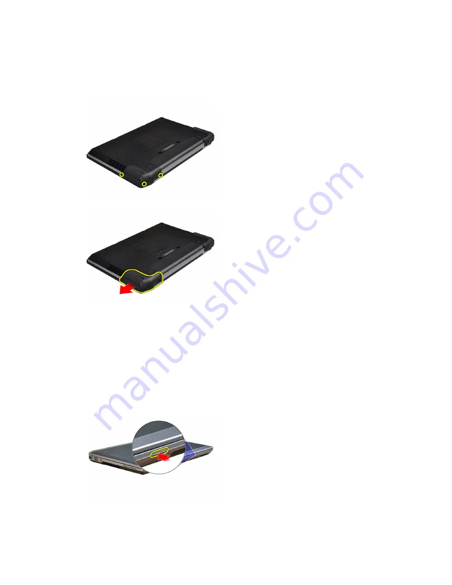
Remove the screws on the right ATG port cover.

3.

Remove the right ATG port cover.

4.

Repeat the steps 1 and 2 to remove the left ATG port cover.

Installing the ATG Port Covers

1.

Place the ATG port covers and tighten the screws that secure it to the computer.

2.

Follow the procedures in 

After Working Inside Your Computer

.

Removing the Secure Digital (SD) Card

1.

Follow the procedures in 

Before Working Inside Your Computer

.

2.

Press in on the SD card to release it from the computer.

12

Содержание Latitude E6430

Страница 1: ...Dell Latitude E6430 E6430 ATG Owner s Manual Regulatory Model P25G Regulatory Type P25G001 P25G002 ...

Страница 2: ...registered trademarks or trademarks of Intel Corporation in the U S and other countries AMD is a registered trademark and AMD Opteron AMD Phenom AMD Sempron AMD Athlon ATI Radeon and ATI FirePro are trademarks of Advanced Micro Devices Inc Microsoft Windows MS DOS Windows Vista the Windows Vista start button and Office Outlook are either trademarks or registered trademarks of Microsoft Corporation...

Страница 3: ...Installing the Battery 14 Removing the Subscriber Identity Module SIM Card 14 Installing the Subscriber Identity Module SIM Card 14 Removing the Base Cover 15 Installing the Base Cover 15 Removing the Keyboard Trim 15 Installing the Keyboard Trim 16 Removing the Keyboard 16 Installing the Keyboard 18 Removing the Hard Drive 19 Installing the Hard Drive 20 Removing the Optical Drive 20 Installing t...

Страница 4: ...t Output I O Board 40 Removing the Hard Drive Support Plate 40 Installing the Hard Drive Support Plate 41 Removing the Palmrest 42 Installing the Palmrest 43 Removing the System Board 44 Installing the System Board 47 Removing the Display Assembly 47 Installing the Display Assembly 50 Removing the Display Bezel 50 Installing the Display Bezel 51 Removing the Display Panel 51 Installing the Display...

Страница 5: ... 72 Assigning a System Password and Setup Password 72 Deleting or Changing an Existing System and or Setup Password 73 5 Diagnostics 75 Enhanced Pre Boot System Assessment ePSA Diagnostics 75 6 Troubleshooting Your Computer 77 Device Status Lights 77 Battery Status Lights 78 7 Technical Specifications 79 8 Contacting Dell 87 ...

Страница 6: ...6 ...

Страница 7: ...face such as a connector on the back of the computer CAUTION Handle components and cards with care Do not touch the components or contacts on a card Hold a card by its edges or by its metal mounting bracket Hold a component such as a processor by its edges not by its pins CAUTION When you disconnect a cable pull on its connector or on its pull tab not on the cable itself Some cables have connector...

Страница 8: ... installed ExpressCards or Smart Cards from the appropriate slots Turning Off Your Computer CAUTION To avoid losing data save and close all open files and exit all open programs before you turn off your computer 1 Shut down the operating system In Windows 8 Using a touch enabled device a Swipe in from the right edge of the screen opening the Charms menu and select Settings b Select the and then se...

Страница 9: ...ot use batteries designed for other Dell computers 1 Connect any external devices such as a port replicator battery slice or media base and replace any cards such as an ExpressCard 2 Connect any telephone or network cables to your computer CAUTION To connect a network cable first plug the cable into the network device and then plug it into the computer 3 Replace the battery 4 Connect your computer...

Страница 10: ...10 ...

Страница 11: ...owing tools Small flat blade screwdriver Phillips screwdriver Small plastic scribe Removing the ATG Handle 1 Follow the procedures in Before Working Inside Your Computer 2 Remove the screws that secure the ATG handle to the computer 3 Remove the right ATG port cover Installing the ATG Handle 1 Secure the ATG handle by tightening it with the screws 2 Follow the procedures in After Working Inside Yo...

Страница 12: ...he steps 1 and 2 to remove the left ATG port cover Installing the ATG Port Covers 1 Place the ATG port covers and tighten the screws that secure it to the computer 2 Follow the procedures in After Working Inside Your Computer Removing the Secure Digital SD Card 1 Follow the procedures in Before Working Inside Your Computer 2 Press in on the SD card to release it from the computer 12 ...

Страница 13: ...king Inside Your Computer Removing the ExpressCard 1 Follow the procedures in Before Working Inside Your Computer 2 Press in on the ExpressCard to release it from the computer 3 Slide the ExpressCard out of the computer Installing the ExpressCard 1 Slide the ExpressCard into its slot until it clicks into place 2 Follow the procedures in After Working Inside Your Computer 13 ...

Страница 14: ...until it clicks into place 2 Follow the procedures in After Working Inside Your Computer Removing the Subscriber Identity Module SIM Card 1 Follow the procedures in Before Working Inside Your Computer 2 Remove the battery 3 Remove the SIM card from the computer Installing the Subscriber Identity Module SIM Card 1 Slide the SIM card into its slot 2 Install the battery 3 Follow the procedures in Aft...

Страница 15: ...ove it from the computer Installing the Base Cover 1 Place the base cover to align with the screw holes on the computer 2 Tighten the screws to secure the base cover to the computer 3 Install the battery 4 Follow the procedures in After Working Inside Your Computer Removing the Keyboard Trim 1 Follow the procedures in Before Working Inside Your Computer 2 Remove the battery 15 ...

Страница 16: ...ard trim from the unit Installing the Keyboard Trim 1 Align the keyboard trim to its slot 2 Press along the sides of the keyboard trim until it clicks in place 3 Install the battery 4 Follow the procedures in After Working Inside Your Computer Removing the Keyboard 1 Follow the procedures in Before Working Inside Your Computer 2 Remove a battery b keyboard trim 16 ...

Страница 17: ...that secure the keyboard to computer 4 Remove the screws that secure the keyboard to the palmrest assembly 5 Lift and turn the keyboard to access the keyboard cable 6 Disconnect the keyboard cable from the system board 17 ...

Страница 18: ...e and secure it to the keyboard using the tape 2 Connect the keyboard cable to the system board 3 Slide the keyboard into its compartment and ensure that it clicks into place 4 Tighten the screws to secure the keyboard on the palmrest 5 Flip the computer and tighten the screws to secure the keyboard 6 Install a keyboard trim b battery 7 Follow the procedures in After Working Inside Your Computer 1...

Страница 19: ...ures in Before Working Inside Your Computer 2 Remove the battery 3 Remove the screws that secure the hard drive to the computer 4 Slide the hard drive out of the computer 5 Remove the screw that secures the hard drive caddy to the hard drive 19 ...

Страница 20: ... drive caddy to the hard drive 3 Tighten the screws to secure the hard drive caddy to the hard drive 4 Slide the hard drive into the computer 5 Tighten the screws to secure the hard drive to the computer 6 Install the battery 7 Follow the procedures in After Working Inside Your Computer Removing the Optical Drive 1 Follow the procedures in Before Working Inside Your Computer 2 Remove the battery 2...

Страница 21: ...optical drive from the computer 4 Pull the optical drive from the computer 5 Remove the screw that secures the optical drive latch to the optical drive assembly 6 Push the optical drive latch forward and remove it from the optical drive assembly 21 ...

Страница 22: ...ical drive 2 Install the latch bracket to the optical drive 3 Tighten the screws to secure the optical drive latch bracket to the optical drive assembly 4 Secure the optical drive latch to the optical drive assembly 5 Tighten the screw to secure the optical drive latch 6 Slide the optical drive into its slot 7 Flip the computer and push in the eject latch to secure the optical drive 8 Install the ...

Страница 23: ...d 5 Repeat steps 2 and 3 to remove the second memory module Installing the Memory 1 Insert the memory module into the memory socket 2 Press the securing clips to secure the memory module to the system board 3 Install a base cover b battery 4 Follow the procedures in After Working Inside Your Computer Removing the Wireless Local Area Network WLAN Card 1 Follow the procedures in Before Working Insid...

Страница 24: ... system board Installing the WLAN Card 1 Insert the WLAN card into its connector at a 45 degree angle into its slot 2 Connect the antenna cables to their respective connectors marked on the WLAN card 3 Tighten the screw to secure the WLAN card to the computer 4 Install a base cover b battery 5 Follow the procedures in After Working Inside Your Computer 24 ...

Страница 25: ... heat sink cable 4 Remove the screws that secure the heat sink to the system board 5 Remove the heat sink from the computer Installing the Heat Sink 1 Slide the heat sink into its original position in the system board 2 Tighten the screws to secure the heat sink to the system board 3 Connect the heat sink cable to the system board 25 ...

Страница 26: ...cover c heat sink 3 Rotate the processor cam lock in a counter clockwise direction 4 Remove the processor from the computer Installing the Processor 1 Align the notches on the processor and the socket and insert the processor into the socket 2 Rotate the processor cam lock in a clockwise direction 3 Install a heat sink b base cover c battery 4 Follow the procedures in After Working Inside Your Com...

Страница 27: ...mputer 2 Remove a battery b hard drive c base cover 3 Remove the screw that secures the bluetooth card to the computer 4 Lift up the card along the bottom edge and remove it from the housing 5 Disconnect the bluetooth cable from the system board and remove the card from the computer 27 ...

Страница 28: ...d in its slot 3 Ensure that it is secured in its slot by tightening the screw 4 Install a base cover b hard drive c battery 5 Follow the procedures in After Working Inside Your Computer Removing the Coin Cell Battery 1 Follow the procedures in Before Working Inside Your Computer 2 Remove a battery b base cover 3 Disconnect the coin cell battery cable 28 ...

Страница 29: ...e 3 Install a base cover b battery 4 Follow the procedures in After Working Inside Your Computer Removing the ExpressCard Cage 1 Follow the procedures in Before Working Inside Your Computer 2 Remove a battery b base cover c hard drive d bluetooth card e keyboard trim f keyboard g display assembly h palmrest 3 Remove the screws that secure the ExpressCard cage to the computer 29 ...

Страница 30: ...ter 3 Install a palmrest b display assembly c keyboard d keyboard trim e bluetooth card f hard drive g base cover h battery 4 Follow the procedures in After Working Inside Your Computer Removing the Media Board 1 Follow the procedures in Before Working Inside Your Computer 2 Remove a battery b base cover c hard drive d bluetooth card e keyboard trim f keyboard g display assembly h palmrest 30 ...

Страница 31: ...he screws that secure the media board to the computer 5 Remove the media board from the computer Installing the Media Board 1 Place the media board in its compartment 2 Tighten the screws to secure the media board 3 Connect the media board cable to the system board 31 ...

Страница 32: ...llow the procedures in After Working Inside Your Computer Removing the Power Connector Port 1 Follow the procedures in Before Working Inside Your Computer 2 Remove a battery b base cover 3 Disconnect the power connector cable from the system board 4 Remove the screw that secures the power connector bracket to the computer 32 ...

Страница 33: ...er 3 Tighten the screw to secure the power connector bracket to the computer 4 Connect the power connector cable to the system board 5 Install a base cover b battery 6 Follow the procedures in After Working Inside Your Computer Removing the Power LED Board 1 Follow the procedures in Before Working Inside Your Computer 2 Remove a battery b base cover c hard drive d bluetooth module e keyboard trim ...

Страница 34: ...lay assembly 5 Remove the power LED board from the display assembly Installing the Power LED Board 1 Place the power LED board in its compartment in the display assembly 2 Tighten the screw to secure the LED board to the display assembly 3 Connect the power LED board cable to the display assembly 34 ...

Страница 35: ...attery 5 Follow the procedures in After Working Inside Your Computer Removing the Modem Card 1 Follow the procedures in Before Working Inside Your Computer 2 Remove a battery b base cover c keyboard trim d keyboard 3 Remove the screw that secures the modem card to the computer 4 Pull out the tab from underneath the palmrest assembly 35 ...

Страница 36: ...modem card from the computer Installing the Modem Card 1 Insert the modem card in its slot 2 Ensure that the modem card is seated 3 Tighten the screw to secure the modem card 4 Install a keyboard b keyboard trim c base cover d battery 5 Follow the procedures in After Working Inside Your Computer 36 ...

Страница 37: ...e a battery b base cover c hard drive d bluetooth card e keyboard trim f keyboard g display assembly h palmrest i media board available in E6430 E6430 ATG only j ExpressCard cage k system board 3 Disconnect the modem card cable from the modem card 4 Remove the modem cable from the routing channel 37 ...

Страница 38: ...puter 7 Remove the modem connector from the computer Installing the Modem Connector 1 Place the modem connector in its compartment 2 Place the modem connector bracket on the connector 3 Tighten the screw to secure the modem connector bracket 4 Route the modem connector cable 5 Connect the modem card cable to the modem card 38 ...

Страница 39: ...ures in After Working Inside Your Computer Removing the Input Output I O Board 1 Follow the procedures in Before Working Inside Your Computer 2 Remove a battery b base cover c hard drive d optical drive e bluetooth card f keyboard trim g keyboard h display assembly i palmrest j media board available in E6430 E6430 ATG only k ExpressCard cage l system board 3 Remove the screw that secures the I O b...

Страница 40: ...d palmrest e display assembly f keyboard g keyboard trim h bluetooth card i hard drive j optical drive k base cover l battery 4 Follow the procedures in After Working Inside Your Computer Removing the Hard Drive Support Plate 1 Follow the procedures in Before Working Inside Your Computer 2 Remove a battery b base cover c hard drive d bluetooth card e keyboard trim f keyboard g display assembly h p...

Страница 41: ...ate 1 Place the hard drive support plate in its compartment 2 Tighten the screws to secure the hard drive support plate to the computer 3 Install a system board b ExpressCard cage c media board d palmrest e display assembly f keyboard g keyboard trim h hard drive i bluetooth card j base cover k battery 4 Follow the procedures in After Working Inside Your Computer 41 ...

Страница 42: ...ry b base cover c hard drive d bluetooth card e keyboard trim f keyboard 3 Remove the screws that secure the palmrest assembly to the base of the computer 4 Flip the computer over and remove the screws that secure the palmrest assembly to the computer 5 Disconnect the LED cable from the system board 42 ...

Страница 43: ...stem board 8 Lift and remove the palmrest from the computer Installing the Palmrest 1 Align the palmrest assembly to its original position in the computer and snap it into place 2 Connect the following cables a SD card b touchpad c LED 3 Tighten the screws to secure the palmrest to the computer 43 ...

Страница 44: ...oard 1 Follow the procedures in Before Working Inside Your Computer 2 Remove a battery b base cover c hard drive d optical drive e bluetooth card f keyboard trim g keyboard h display assembly i palmrest j media board k ExpressCard cage 3 Disconnect the coin cell battery cable from the base of the system board 4 Disconnect the camera cable from the base of the system board 44 ...

Страница 45: ...crew securing the LVDS cable bracket 6 Remove the LVDS cable bracket from the computer 7 Disconnect the LVDS cable from the back of the system board 8 Disconnect the speaker cable from the base of the system board 45 ...

Страница 46: ...secure the system board to the computer 11 Gently lift the left edge of the system board assembly and raise it to a 45 degree angle and release the system board from the port connectors on the right 12 Release the system board from the connector port on the back and remove the system board from the system 46 ...

Страница 47: ...ew to secure the LVDS cable bracket 6 Install the a ExpressCard cage b media board c palmrest d display assembly e keyboard f keyboard trim g bluetooth card h optical drive i hard drive j base cover k battery 7 Follow the procedures in After Working Inside Your Computer Removing the Display Assembly 1 Follow the procedures in Before Working Inside Your Computer 2 Remove a battery b base cover c ke...

Страница 48: ...upport bracket from the computer 5 Pull upwards on the tab to disconnect the LVDS cable from the computer 6 Disconnect the camera cable from the computer 7 Remove the LVDS and camera cable from the routing channel 48 ...

Страница 49: ... any antennas connected to wireless solutions 9 Remove any antennas from the routing channel 10 Remove the screws that secure the display assembly to the computer 11 Remove the display assembly from the computer 49 ...

Страница 50: ...o the computer 7 Connect the LVDS cable to the computer 8 Install the LVDS support bracket in its position on the computer 9 Tighten the screw to secure the support bracket to the computer 10 Install a keyboard b keyboard trim c base cover d battery 11 Follow the procedures in After Working Inside Your Computer Removing the Display Bezel 1 Follow the procedures in Before Working Inside Your Comput...

Страница 51: ...ntire bezel until it clicks onto the display assembly 3 Press on the left and right edges of the display bezel 4 Install the battery 5 Follow the procedures in After Working Inside Your Computer Removing the Display Panel 1 Follow the procedures in Before Working Inside Your Computer 2 Remove a battery b display assembly c display bezel 3 Remove the screws that secure the display panel to the disp...

Страница 52: ... display assembly Installing the Display Panel 1 Connect the LVDS cable and stick the LVDS cable connector tape 2 Flip the display and place it in the display assembly 3 Tighten the screws to secure the display panel to the display assembly 4 Install a display bezel b display assembly c battery 5 Follow the procedures in After Working Inside Your Computer 52 ...

Страница 53: ...display assembly 3 Rotate the left and right hinges upwards to a vertical position 4 Pry loose the edge of hinge cap from the hinge and remove the hinge caps from the display assembly Installing the Display Hinge Caps 1 Slide the left hinge cap on the display panel 2 Rotate the hinge downward to secure the hinge cap to the display panel 3 Repeat steps 1 and 2 for the right hinge cap 53 ...

Страница 54: ...ur Computer Removing the Display Hinges 1 Follow the procedures in Before Working Inside Your Computer 2 Remove a battery b base cover c hard drive d bluetooth card e keyboard trim f keyboard g display assembly h display bezel i display panel 3 Remove the screws that secure the display hinge plates to the display assembly 4 Remove the display hinge plates 54 ...

Страница 55: ...2 Tighten the screws to secure the display hinges to the display assembly 3 Place the display hinge plates on the hinges 4 Tighten the screws to secure the display hinge plates to the display assembly 5 Install a display panel b display bezel c display assembly d keyboard e keyboard trim f bluetooth card g hard drive h base cover i battery 6 Follow the procedures in After Working Inside Your Compu...

Страница 56: ...bezel d display panel 3 Disconnect the LVDS and camera cable from the camera 4 Remove the screw that secures the camera to the display assembly 5 Remove the camera from the display assembly Installing the Camera 1 Install the camera in its slot on the display panel 2 Tighten the screw to secure the camera to the display assembly 56 ...

Страница 57: ...ving the LVDS and Camera Cable 1 Follow the procedures in Before Working Inside Your Computer 2 Remove a battery b base cover c hard drive d bluetooth card e keyboard trim f keyboard g display assembly h display bezel i display panel j display hinges 3 Disconnect the LVDS and camera cable from the camera 4 Peel back the adhesives securing the LVDS and camera cable to the display assembly 57 ...

Страница 58: ... b display panel c display bezel d display assembly e keyboard f keyboard trim g bluetooth card h hard drive i base cover j battery 5 Follow the procedures in After Working Inside Your Computer Removing the Speakers 1 Follow the procedures in Before Working Inside Your Computer 2 Remove a battery b base cover c hard drive d keyboard trim e keyboard f display assembly g palmrest h media board avail...

Страница 59: ...he computer 4 Remove the speaker cable from the routing channel 5 Remove the speakers from the computer Installing the Speakers 1 Align the speakers in the original position and connect the speaker cables 2 Tighten the screws to secure the speakers 59 ...

Страница 60: ...ooth card c ExpressCard cage d media board available in E6430 E6430 ATG only e palmrest f display assembly g keyboard h keyboard trim i hard drive j base cover k battery 4 Follow the procedures in After Working Inside Your Computer 60 ...

Страница 61: ...3 Docking Port Information The docking port is used for connecting the laptop to a docking station optional 1 Docking Port 61 ...

Страница 62: ...62 ...

Страница 63: ...ess System Setup by pressing F2 key Bring up the one time boot menu by pressing F12 key The one time boot menu displays the devices that you can boot from including the diagnostic option The boot menu options are Removable Drive if available STXXXX Drive NOTE XXX denotes the SATA drive number Optical Drive Diagnostics NOTE Choosing Diagnostics will display the ePSA diagnostics screen The boot sequ...

Страница 64: ...section may or may not appear Table 2 General Option Description System Information This section lists the primary hardware features of your computer System Information Memory Information Processor Information Device Information Battery Information Displays the charge status of the battery Boot Sequence Allows you to change the order in which the computer attempts to find an operating system All t...

Страница 65: ...esources even if the setting is disabled SATA Operation Allows you to configure the internal SATA hard drive controller The options are Disabled ATA AHCI RAID On Default Setting NOTE SATA is configured to support RAID mode Drives Allows you to configure the SATA drives on board The options are SATA 0 SATA 1 SATA 4 SATA 5 Default Setting All drives are enabled SMART Reporting This field controls wh...

Страница 66: ... operating mode of the keyboard illumination feature The options are Disabled Default Setting Level is 25 Level is 50 Level is 75 Level is 100 Stealth Mode Control Allows you to set the mode that turns off all light and sound emissions from the system This option is disabled by default Enable Stealth Mode Miscellaneous Devices Allows you enable or disable the various on board devices The options a...

Страница 67: ...D 0 Password Allows you to set change or delete the administrator admin password Default Setting Not set Strong Password Allows you to enforce the option to always set strong passwords Default Setting Enable Strong Password is not selected Password Configuration You can define the length of your password Min 4 Max 32 Password Bypass Allows you to enable or disable the permission to bypass the Syst...

Страница 68: ...sers from entering Setup when an Administrator password is set Default Setting Disabled Table 6 Performance Option Description Multi Core Support This field specifies whether the process will have one or all cores enabled The performance of some applications will improve with the additional cores This option is enabled by default Allows you to enable or disable multi core support for the processor...

Страница 69: ... Default Setting both the options are disabled Wake on LAN WLAN This option allows the computer to power up from the off state when triggered by a special LAN signal Wake up from the Standby state is unaffected by this setting and must be enabled in the operating system This feature only works when the computer is connected to AC power supply Disabled Does not allow the system to power on by speci...

Страница 70: ...use Touchpad PS 2 Mouse Default Setting Numlock Enable Specifies if the NumLock function can be enabled when the computer boots This option is enabled by default Enable Numlock Fn Key Emulation Allows you to match the Scroll Lock key feature of PS 2 keyboard with the Fn key feature in an internal keyboard The option is enabled by default Enable Fn Key Emulation Keyboard Errors Specifies whether ke...

Страница 71: ...Setting Table 10 Wireless Option Description Wireless Switch Allows you to determine which wireless device can be controlled by the wireless switch The options are WWAN Bluetooth WLAN All options are enabled by default Wireless Device Enable Allows you to enable or disable the wireless devices The options are WWAN Bluetooth WLAN All options are enabled by default Table 11 Maintenance Option Descri...

Страница 72: ...lick Analyze System for Updates and follow the instructions on the screen 10 Select your preferred download method in the Please select your download method below window click Download File The File Download window appears 11 Click Save to save the file on your computer 12 Click Run to install the updated BIOS settings on your computer Follow the instructions on the screen System and Setup Passwor...

Страница 73: ...p password that you entered earlier and click OK 7 Press Esc and a message prompts you to save the changes 8 Press Y to save the changes The computer reboots Deleting or Changing an Existing System and or Setup Password Ensure that the Password Status is Unlocked in the System Setup before attempting to delete or change the existing System and or Setup password You cannot delete or change an exist...

Страница 74: ...74 ...

Страница 75: ... provide extra information about the failed device s View status messages that inform you if tests are completed successfully View error messages that inform you of problems encountered during testing CAUTION Use the system diagnostics to test only your computer Using this program with other computers may cause invalid results or error messages NOTE Some tests for specific devices require user int...

Страница 76: ...76 ...

Страница 77: ...ure to the system The following table lists how to read the LED codes when possible errors occur Table 14 LED Lights Storage LED Power LED Wireless LED Fault Description Blinking Solid Solid A possible processor failure has occurred Solid Blinking Solid The memory modules are detected but has encountered an error Blinking Blinking Blinking A system board failure has occurred Blinking Blinking Soli...

Страница 78: ...ated or unsupported non Dell AC adapter is attached to your laptop Alternately blinking amber light with steady white light Temporary battery failure with AC adapter present Constantly blinking amber light Fatal battery failure with AC adapter present Light off Battery in full charge mode with AC adapter present White light on Battery in charge mode with AC adapter present 78 ...

Страница 79: ...ort in your Windows operating system and select the option to view information about your computer Table 15 System Information Feature Specification Chipset Mobile Intel 7 series chipset Intel QM77 DRAM bus width 64 bit Flash EPROM SPI 32 MB 64 MB PCIe Gen1 bus 100 MHz External Bus Frequency DMI 5GT s Table 16 Processor Feature Specification Types Intel Core i3 i5 i7series L3 cache up to 8 MB Tabl...

Страница 80: ...it operating systems Table 18 Audio Feature Specification Type four channel high definition audio Controller IDT92HD93 Stereo conversion 24 bit analog to digital and digital to analog Interface Internal high definition audio External microphone in stereo headphones external speakers connector Speakers two Internal speaker amplifier 1 W RMS per channel Volume controls keyboard function keys program...

Страница 81: ...e 22 Contactless Smart Card Feature Specification Supported Smart Cards Technologies ISO14443A 106 kbps 212 kbps 424 kbps and 848 kbps ISO14443B 106 kbps 212 kbps 424 kbps and 848 kbps ISO15936 HID iClass FIPS201 NXP Desfire HID iClass FIPS201 NXP Desfire Table 23 Display Feature Specification Type HD 1366x768 WLED HD 1600 x 900 FHD 1920 x 1080 Size Latitude E6430 14 0 Latitude E6530 15 6 Latitude...

Страница 82: ...ightness 220 nits Latitude E6430 ATG Height 192 5 mm 7 57 inches Width 324 mm 12 75 inches Diagonal 355 60 mm 14 00 inches Active area X Y 357 30 mm x 246 50 mm Maximum resolution 1366 x 768 pixels Maximum Brightness 730 nits Operating angle 0 closed to 180 Refresh rate 60 Hz Minimum Viewing Angles Latitude E6430 Latitude E6530 Horizontal 40 Vertical 10 30 Latitude E6430 ATG Horizontal 50 Vertical...

Страница 83: ...ion Type 4 cell 40 WHr Lithium ion battery with Express Charge selected countries only 6 cell 60 WHr Lithium ion battery with Express Charge 9 cell 97 WHr Lithium ion battery with Express Charge 9 cell 87 WHr Lithium ion battery Dimensions 4 cell 6 cell Depth 48 08 mm 1 90 inches Height 20 00 mm 0 79 inches Width 208 00 mm 8 18 inches 9 cell Depth 71 79 mm 2 83 inches Height 20 00 mm 0 79 inches W...

Страница 84: ...nge Operating 0 C to 40 C 32 F to 104 F 0 C to 40 C 32 F to 104 F Non Operating 40 C to 70 C 40 F to 158 F 40 C to 70 C 40 F to 158 F Table 28 Physical Feature Latitude E6430 Latitude E6530 Latitude E6430 ATG Height 26 90 mm to 32 40 mm 1 06 inches to 1 27 inches 28 40 mm to 34 20 mm 1 11 inches to 1 35 inches 29 50 mm to 37 70 mm 1 16 inches to 1 48 inches Width 352 00 mm 13 86 inches 384 00 mm 1...

Страница 85: ...10 to 90 non condensing Storage 5 to 95 non condensing Altitude maximum Operating 15 24 m to 3048 m 50 ft to 10 000 ft Non Operating 15 24 m to 10 668 m 50 ft to 35 000 ft Airborne contaminant level G1 as defined by ISA 71 04 1985 85 ...

Страница 86: ...86 ...

Страница 87: ...port dell com 2 Verify your country or region in the Choose a Country Region drop down menu at the bottom of the page 3 Click Contact Us on the left side of the page 4 Select the appropriate service or support link based on your need 5 Choose the method of contacting Dell that is convenient for you 87 ...

Отзывы: