


Removing the Heatsink
1.
Follow the procedures in
Before Working Inside Your Computer
.
2.
Remove:
a) SD card
b) battery
c) base cover
d) keyboard trim
e) keyboard
f) memory
g) optical drive
h) hard drive
i) hard-drive cage
j) WLAN card
k) display hinge
l) palmrest
m) system fan
n) ExpressCard cage
o) system board
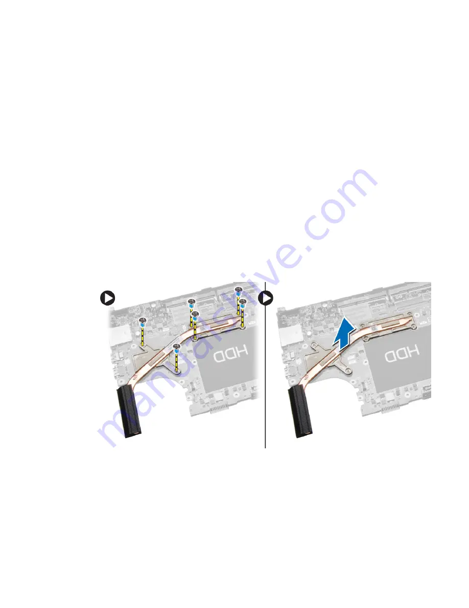
3.
Perform the following steps:
a) Remove the screws that secure the heatsink in place.
b) Lift to remove the heatsink from the computer.
Installing the Heatsink
1.
Place the heatsink on the system board.
2.
Tighten the screws to secure the heatsink to the computer.
31
Содержание Latitude E5540
Страница 1: ...Dell Latitude E5540 Owner s Manual Regulatory Model P44G Regulatory Type P44G001 ...
Страница 8: ...5 Turn on your computer 8 ...
Страница 54: ...54 ...