background image

2

Removing and Installing Components

This section provides detailed information on how to remove or install the components from your 

computer.

Recommended Tools

The procedures in this document may require the following tools:

• Small flat-blade screwdriver
• #0 Phillips screwdriver
• #1 Phillips screwdriver
• Small plastic scribe
• Flash BIOS update program CD

System Overview

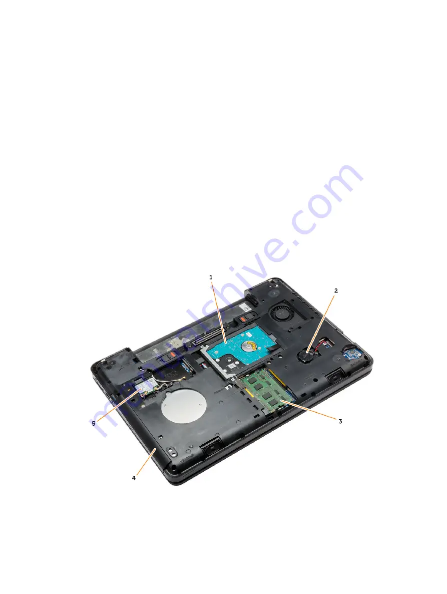
Figure 1. Inside View — Back

9

Содержание Latitude E5440

Страница 1: ...Dell Latitude E5440 Owner s Manual Regulatory Model P44G Regulatory Type P44G001 ...

Страница 2: ...henom and AMD Sempron are trademarks of Advanced Micro Devices Inc Microsoft Windows Windows Server Internet Explorer MS DOS Windows Vista and Active Directory are either trademarks or registered trademarks of Microsoft Corporation in the United States and or other countries Red Hat and Red Hat Enterprise Linux are registered trademarks of Red Hat Inc in the United States and or other countries No...

Страница 3: ... the Display Bezel 12 Installing the Display Bezel 13 Removing the Display Panel 13 Installing the Display Panel 14 Removing the Camera 14 Installing the Camera 15 Removing the Keyboard Trim 15 Installing the Keyboard Trim 15 Removing the Keyboard 16 Installing the Keyboard 17 Removing the Base Cover 18 Installing the Base Cover 18 Removing the Optical Drive 18 Installing the Optical Drive 19 Remo...

Страница 4: ...rd Left 36 Removing the I O Board Right 36 Installing the I O Board Right 37 Removing the Power Connector 37 Installing the Power Connector 38 Removing the Speakers 38 Installing the Speakers 39 Removing the Status Light Board 40 Installing the Status Light Board 40 3 System Setup 43 Boot Sequence 43 Navigation Keys 43 System Setup Options 44 Updating the BIOS 54 System and Setup Password 54 Assig...

Страница 5: ...e with the product CAUTION To avoid electrostatic discharge ground yourself by using a wrist grounding strap or by periodically touching an unpainted metal surface such as a connector on the back of the computer CAUTION Handle components and cards with care Do not touch the components or contacts on a card Hold a card by its edges or by its metal mounting bracket Hold a component such as a process...

Страница 6: ...isplay CAUTION Before touching anything inside your computer ground yourself by touching an unpainted metal surface such as the metal at the back of the computer While you work periodically touch an unpainted metal surface to dissipate static electricity which could harm internal components 11 Remove any installed ExpressCards or Smart Cards from the appropriate slots Turning Off Your Computer CAU...

Страница 7: ...external devices cards and cables before turning on your computer CAUTION To avoid damage to the computer use only the battery designed for this particular Dell computer Do not use batteries designed for other Dell computers 1 Connect any external devices such as a port replicator battery slice or media base and replace any cards such as an ExpressCard 2 Connect any telephone or network cables to ...

Страница 8: ...8 ...

Страница 9: ...e or install the components from your computer Recommended Tools The procedures in this document may require the following tools Small flat blade screwdriver 0 Phillips screwdriver 1 Phillips screwdriver Small plastic scribe Flash BIOS update program CD System Overview Figure 1 Inside View Back 9 ...

Страница 10: ...r 2 I O board left 3 system fan 4 ExpressCard cage 5 speakers 6 status light board 7 system board 8 I O board right Removing the Battery 1 Follow the procedures in Before Working Inside Your Computer 2 Perform the following steps a Slide the battery release latches into the unlock position b Push and remove the battery from the computer 10 ...

Страница 11: ... card to release it from the computer 3 Slide the SD card out of the computer Installing the SD Card 1 Push the SD card into the compartment until it clicks into place 2 Follow the procedures in After Working Inside Your Computer Removing the ExpressCard 1 Follow the procedures in Before Working On Your Computer 2 Perform the following steps a Push in on the ExpressCard to release from the compute...

Страница 12: ...ery wall 4 Slide the SIM card from the computer NOTE The SIM slot in the computer supports only micro SIM Installing the SIM Card 1 Insert the SIM card into the slot 2 Install the battery 3 Follow the procedures in After Working Inside Your Computer Removing the Display Bezel 1 Follow the procedures in Before Working Inside Your Computer 2 Remove the battery 3 Perform the following steps a Pry up ...

Страница 13: ...d work around the entire bezel until it snaps onto the display assembly 3 Install the battery 4 Follow the procedures in After Working Inside Your Computer Removing the Display Panel 1 Follow the procedures in Before Working Inside Your Computer 2 Remove a battery b display bezel 3 Remove the screws that secure the display panel and flip the panel over 4 Perform the following steps 13 ...

Страница 14: ...ial signaling LVDS cable to the display panel and attach the tape 4 Flip the display panel over and tighten the screws to secure the display panel 5 Install a display bezel b battery 6 Follow the procedures in After Working Inside Your Computer Removing the Camera 1 Follow the procedures in Before Working Inside Your Computer 2 Remove a battery b display bezel 3 Perform the following steps a Remov...

Страница 15: ...ter Working Inside Your Computer Removing the Keyboard Trim 1 Follow the procedures in Before Working Inside Your Computer 2 Remove the battery 3 Perform the following steps a Pry up the keyboard trim on its sides and the top edge b Lift upwards and remove the keyboard trim from the computer Installing the Keyboard Trim 1 Align the keyboard trim to its place 2 Press along the sides of the keyboard...

Страница 16: ...oving the Keyboard 1 Follow the procedures in Before Working Inside Your Computer 2 Remove a battery b keyboard trim 3 Remove the screws at the back of the computer and flip the computer over 4 Remove the screws that secure the keyboard 1 and lift the keyboard from the computer 2 and 3 16 ...

Страница 17: ... 2 Place the keyboard into its place until all the metal tabs fit into their positions 3 Press down on the keyboard to the left and right side ensuring that all the snaps are fully engaged with the computer 4 Install the screws to secure the keyboard to the palmrest 5 Install the screws at the back of the computer 6 Install a keyboard trim 17 ...

Страница 18: ...the computer Installing the Base Cover 1 Slide the base cover into its slot until it clicks into place 2 Install the screws that secure the base cover to the computer 3 Install the battery 4 Follow the procedures in After Working Inside Your Computer Removing the Optical Drive 1 Follow the procedures in Before Working Inside Your Computer 2 Remove a battery b base cover 3 Perform the following ste...

Страница 19: ...om the optical drive 6 Remove the optical drive bezel Installing the Optical Drive 1 Engage the optical drive bezel tabs to attach the optical drive bezel to the optical drive 2 Install the optical drive bracket 3 Tighten the screws to secure the optical drive bracket 4 Insert the optical drive into the computer 5 Tighten the screw to secure the optical drive in its place 6 Install a base cover b ...

Страница 20: ...base cover 3 Perform the following steps a Remove the screws that secure the hard drive bracket in place b Slide and pull the hard drive to remove from its connectors 4 Remove the hard drive isolation cap from the hard drive Installing the Hard Drive 1 Engage the hard drive isolation cap to the hard drive 20 ...

Страница 21: ...ur Computer Removing the Memory Module 1 Follow the procedures in Before Working Inside Your Computer 2 Remove a battery b base cover 3 Pry the retention clips away from the memory module until it pops up 4 Lift up the memory module and remove it from the computer Installing the Memory Module 1 Insert the memory into the memory socket 2 Press the clips to secure the memory module to the system boa...

Страница 22: ... the WLAN Card 1 Insert the WLAN card into its connector on the system board 2 Connect the antenna cables to the respective connectors marked on the WLAN card 3 Tighten the screw to secure the WLAN card to the computer 4 Install a base cover b battery 5 Follow the procedures in After Working Inside Your Computer Removing the Coin Cell Battery 1 Follow the procedures in Before Working Inside Your C...

Страница 23: ...the procedures in After Working Inside Your Computer Removing the Display Hinge 1 Follow the procedures in Before Working Inside Your Computer 2 Remove a battery b base cover c keyboard trim d keyboard 3 Remove the screws that secure the display hinge at the back of the computer 4 Remove the screws that secure the display hinge at the front of the computer Press and remove the display hinge from t...

Страница 24: ... keyboard b keyboard trim c base cover d battery 4 Follow the procedures in After Working Inside Your Computer Removing the Palmrest 1 Follow the procedures in Before Working Inside Your Computer 2 Remove a SD card b battery c base cover d keyboard trim e keyboard f memory g optical drive h hard drive i display hinge 3 Remove the screws at the bottom of the computer 24 ...

Страница 25: ...buttons cable b touch pad cable c fingerprint scanner cable d power button cable 5 Perform the following steps a Remove the screws that secure the palmrest of the computer b Lift and remove the palmrest from the computer 25 ...

Страница 26: ...media button cable 3 Tighten the screws to secure the palmrest at the front and back of the computer 4 Install a display hinge b hard drive c optical drive d memory e keyboard f keyboard trim g base cover h battery i SD card 5 Follow the procedures in After Working Inside Your Computer Removing the Display Assembly 1 Follow the procedures in Before Working Inside Your Computer 2 Remove a SD card b...

Страница 27: ... Perform the following steps a Remove the screw that secures the display cable connector and remove it from the system board b Disconnect the display cables from the system board 5 Remove the screws that secure the display assembly in place and lift to remove the display assembly from the computer 27 ...

Страница 28: ...e the display cable along its compartment and connect the display cables to its connectors on the system board 4 Connect the WLAN cables to their connectors 5 Install a palmrest b display hinge c keyboard d keyboard trim e base cover f battery g SD card 6 Follow the procedures in After Working Inside Your Computer Removing the ExpressCard Cage 1 Follow the procedures in Before Working Inside Your ...

Страница 29: ...puter and snap it into place 2 Install the screws that secure the ExpressCard cage 3 Install a palmrest b display hinge c keyboard d keyboard trim e base cover f battery g SD card 4 Follow the procedures in After Working Inside Your Computer Removing the System Fan 1 Follow the procedures in Before Working Inside Your Computer 2 Remove a SD card b battery c base cover d keyboard trim e keyboard f ...

Страница 30: ...emove from the computer Installing the System Fan 1 Place the system fan on the computer 2 Connect the system fan cable to the system board 3 Connect the I O board cable to its connector 4 Tighten the screws to secure the system fan on the computer 5 Install a palmrest b display hinge c memory d hard drive e optical drive 30 ...

Страница 31: ...es in Before Working Inside Your Computer 2 Remove a SD card b battery c base cover d keyboard trim e keyboard f memory g optical drive h hard drive i WLAN card j display hinge k palmrest l system fan m ExpressCard cage 3 Disconnect a coin cell battery cable b speaker cable 4 Flip the computer and disconnect a power cable b status light board cable c I O board cable 31 ...

Страница 32: ...secure the display cable connector and remove it from the system board b Disconnect the display cables and power connector cable from the system board 6 Remove the screws that secure the system board and lift the system board to remove from the computer 32 ...

Страница 33: ... board cable b power connector cable c status light board cable 4 Turn over the computer and connect the coin cell battery cable and speaker cable to the system board 5 Install a ExpressCard cage b system fan c palmrest d display hinge e WLAN card f hard drive g optical drive h memory i keyboard j keyboard trim k base cover l battery m SD card 6 Follow the procedures in After Working Inside Your C...

Страница 34: ...AN card j display hinge k palmrest l system fan m ExpressCard cage n system board 3 Perform the following steps a Remove the screws that secure the heatsink in place b Lift to remove the heatsink from the computer Installing the Heatsink 1 Place the heatsink on the system board 2 Tighten the screws to secure the heatsink to the computer 3 Install a system board b ExpressCard cage c system fan 34 ...

Страница 35: ... Board Left 1 Follow the procedures in Before Working Inside Your Computer 2 Remove a SD card b battery c base cover d keyboard trim e keyboard f memory g optical drive h hard drive i WLAN card j display hinge k palmrest l system fan m ExpressCard cage n system board 3 Perform the following steps a Remove the screw that secures the left I O board on the computer b Lift the I O board and remove fro...

Страница 36: ...ttery n SD card 4 Follow the procedures in After Working Inside Your Computer Removing the I O Board Right 1 Follow the procedures in Before Working Inside Your Computer 2 Remove a SD card b battery c base cover d keyboard trim e keyboard f memory g optical drive h hard drive i WLAN card j display hinge k palmrest l system fan m ExpressCard cage n system board 3 Perform the following steps a Remov...

Страница 37: ... display hinge f WLAN card g hard drive h optical drive i memory j keyboard k keyboard trim l base cover m battery n SD card 4 Follow the procedures in After Working Inside Your Computer Removing the Power Connector 1 Follow the procedures in Before Working Inside Your Computer 2 Remove a SD card b battery c base cover d keyboard trim e keyboard f memory g hard drive h optical drive i WLAN card 37...

Страница 38: ...place in the computer 2 Route the power connector cable on its routing channels 3 Install a system board b system fan c ExpressCard cage d palmrest e display hinge f WLAN card g hard drive h optical drive i memory j keyboard k keyboard trim l base cover m battery n SD card 4 Follow the procedures in After Working Inside Your Computer Removing the Speakers 1 Follow the procedures in Before Working ...

Страница 39: ...b Remove the screws that secure the speakers from the computer c Lift and remove the speakers from the computer Installing the Speakers 1 Place the speakers on the computer 2 Secure the speaker cable to the routing channels 3 Tighten the screws to secure the speakers to the computer 4 Install a system board b ExpressCard cage c system fan d palmrest e display hinge f WLAN card g hard drive h optic...

Страница 40: ...e k palmrest l system fan m ExpressCard cage n system board o speakers 3 Perform the following steps a Remove the LED cover b Disconnect the status light board cable and remove the screw that secures the status light board c Lift and remove the status light board from the computer Installing the Status Light Board 1 Place the status light board on its place on the computer 2 Connect the status lig...

Страница 41: ...d c system fan d ExpressCard cage e palmrest f display hinge g WLAN card h hard drive i optical drive j memory k keyboard l keyboard trim m base cover n battery o SD card 6 Follow the procedures in After Working Inside Your Computer 41 ...

Страница 42: ...42 ...

Страница 43: ...on Self Test POST when the Dell logo appears you can Access System Setup by pressing F2 key Bring up the one time boot menu by pressing F12 key The one time boot menu displays the devices that you can boot from including the diagnostic option The boot menu options are Removable Drive if available STXXXX Drive NOTE XXX denotes the SATA drive number Optical Drive Diagnostics NOTE Choosing Diagnostic...

Страница 44: ...Information Displays BIOS Version Service Tag Asset Tag Ownership Tag Ownership Date Manufacture Date and the Express Service Code Memory Information Displays Memory Installed Memory Available Memory Speed Memory Channels Mode Memory Technology DIMM ASize DIMM B Size Processor Information Displays Processor Type Core Count Processor ID Current Clock Speed Minimum Clock Speed Maximum Clock Speed Pr...

Страница 45: ...on Description Integrated NIC Allows you to configure the integrated network controller The options are Disabled Enabled Enabled w PXE This option is enabled by default Parallel Port Allows you to configure the parallel port on the docking station The options are Disabled AT This option is enabled by default PS2 ECP Serial Port Allows you to configure the integrated serial port The options are Dis...

Страница 46: ...rt is disabled the OS cannot see any device attached to this port Enable Boot Support Enable External USB Port Enable USB3 0 Controller NOTE USB keyboard and mouse always work in the BIOS setup irrespective of these settings Audio This field enables or disables the integrated audio controller By default the Enable Audio option is selected Keyboard Illumination This field lets you choose the operat...

Страница 47: ...nges take effect immediately Default Setting Not set System Password Allows you to set change or delete the system password NOTE Successful password changes take effect immediately Default Setting Not set Internal HDD 1 Password Allows you to set or change the system s internal hard disk drive NOTE Successful password changes take effect immediately Default Setting Not set Strong Password Allows y...

Страница 48: ... the optional Computrace software The options are Deactivate Disable Activate NOTE The Activate and Disable options will permanently activate or disable the feature and no further changes will be allowed Deactivate default CPU XD Support Allows you to enable the Execute Disable mode of the processor Enable CPU XD Support default OROM Keyboard Access Allows you to set an option to enter the Option ...

Страница 49: ...ased and the keys will restore to default settings Table 7 Performance Option Description Multi Core Support This field specifies whether the process will have one or all cores enabled The performance of some applications will improve with the additional cores This option is enabled by default Allows you to enable or disable multi core support for the processor The options are All 1 2 Default Sett...

Страница 50: ...when the AC power adapter is connected If the AC power adapter is removed during Standby the system setup will remove power from all of the USB ports to conserve battery power Enable USB Wake Support DEnable USB Wake Support is not selected Wireless Radio Control Allows you to enable or disable the feature that automatically switches from wired or wireless networks without depending on the physica...

Страница 51: ... this option disable the Advanced Battery Charge Configuration option Battery Slice Charge Configuration Allows you to select the type of charge for the battery The options are Standard Charge Express Charge This option is enabled by default NOTE Express charge may not be available for all the batteries To enable this option disable the Advanced Battery Charge Configuration option Intel Smart Conn...

Страница 52: ...e of the compatibility steps The options are Minimal Thorough default Auto Extended BIOS POST Time Allows you to create an additional pre boot delay The options are 0 seconds 5 seconds default 10 seconds Table 10 Virtualization Support Option Description Virtualization Allows you to enable or disable the Intel Virtualization Technology Enable Intel Virtualization Technology default VT for Direct I...

Страница 53: ...devices Latitude E5440 WWAN WLAN WiGig Bluetooth All the options are enabled by default Latitude E5540 WLAN WiGig Bluetooth All the options are enabled by default Table 12 Maintenance Option Description Service Tag Displays the Service Tag of your computer Asset Tag Allows you to create a system asset tag if an asset tag is not already set This option is not set by default Table 13 System Logs Opt...

Страница 54: ... Drivers and Downloads screen under the Operating System drop down list select BIOS 10 Identify the latest BIOS file and click Download File 11 Select your preferred download method in the Please select your download method below window click Download File The File Download window appears 12 Click Save to save the file on your computer 13 Click Run to install the updated BIOS settings on your comp...

Страница 55: ...that you entered earlier and click OK 5 Select Setup Password type your system password and press Enter or Tab A message prompts you to re type the setup password 6 Type the setup password that you entered earlier and click OK 7 Press Esc and a message prompts you to save the changes 8 Press Y to save the changes The computer reboots Deleting or Changing an Existing System and or Setup Password En...

Страница 56: ...6 Press Y to save the changes and exit from the System Setup The computer reboots 56 ...

Страница 57: ... provide extra information about the failed device s View status messages that inform you if tests are completed successfully View error messages that inform you of problems encountered during testing CAUTION Use the system diagnostics to test only your computer Using this program with other computers may cause invalid results or error messages NOTE Some tests for specific devices require user int...

Страница 58: ...mputer is connected to an electrical outlet the battery light operates as follows Alternately blinking amber light and white light An unauthenticated or unsupported non Dell AC adapter is attached to your laptop Alternately blinking amber light with steady white light Temporary battery failure with AC adapter present Constantly blinking amber light Fatal battery failure with AC adapter present Lig...

Страница 59: ...ency DMI 5GT s Table 15 Processor Feature Specification Types Intel Core i3 series Intel Core i5 series Intel Core i7 series L3 cache up to 8 MB Table 16 Memory Feature Specification Memory connector two SoDIMM slots Memory capacity 2 GB 4 GB or 8 GB Memory type DDR3L SDRAM 1600 Minimum memory 2 GB Maximum memory 8 GB Table 17 mSATA Support Feature Specification with Express Card I O and Discrete ...

Страница 60: ...s connector Speakers two Internal speaker amplifier 1W RMS per channel Volume controls keyboard function keys program menus Table 19 Video Feature Specification Type integrated on system board Controller UMA Intel HD Graphics 4400 Discrete nVidia GeForce GT 720M 2GB Graphics Table 20 Communications Feature Specification Network adapter 10 100 1000 Mb s Ethernet RJ 45 Wireless Internal wireless loc...

Страница 61: ... reader one 8 in 1 memory card reader Docking port one Subscriber Identity Module SIM port one E5440 only Table 22 Display Feature Specification Type Latitude E5440 HD 1366x768 WLED HD 1600 x 900 Latitude E5540 HD 1366x768 WLED FHD 1920 x 1080 Size Latitude E5440 14 0 Latitude E5540 15 6 Dimensions Latitude E5440 Height 192 5 mm 7 57 inches Width 324 mm 12 75 inches Diagonal 355 60 mm 14 00 inches...

Страница 62: ...HD 60 for FHD Vertical 10 30 for HD 50 for FHD Pixel pitch Latitude E5440 0 2265 mm x 0 2265 mm Latitude E5540 0 2520 mm x 0 2520 mm for HD 0 1790 x 0 1790 for FHD Table 23 Keyboard Feature Specifcation Number of keys United States 86 keys United Kingdom 87 keys Brazil 87 keys and Japan 90 keys Layout QWERTY AZERTY Kanji Table 24 Touchpad Feature Specification Active Area X axis 80 00 mm 3 15 inch...

Страница 63: ...0 C to 85 C 40 F to 185 F NOTE The battery pack is capable of safely withstanding the above storage temperatures with 100 charge NOTE The battery pack is also capable of withstanding storage temperatures from 20 C to 60 C with no degradation in its performance Coin cell battery 3 V CR2032 lithium coin cell Table 26 AC Adapter Feature Latitude E5440 Latitude E5540 Type 65 W 90 W adapter Input volta...

Страница 64: ...25 mm 1 11 inches Back 33 60 mm 1 32 inches Front 26 00 mm 1 02 inches Back 29 70 mm 1 17 inches Width 338 00 mm 13 31 inches 379 00 mm 14 92 inches Depth 235 00 mm 9 25 inches 250 50 mm 9 86 inches Weight minimu m 1 99 kg 4 40 lb 2 42 kg 5 35 lb Table 28 Environmental Feature Specification Temperature Operating 0 C to 35 C 32 F to 95 F Storage 40 C to 65 C 40 F to 149 F Relative humidity maximum ...

Страница 65: ...ed support and service options Availability varies by country and product and some services may not be available in your area To contact Dell for sales technical support or customer service issues 1 Visit dell com support 2 Select your support category 3 Verify your country or region in the Choose a Country Region drop down menu at the top of page 4 Select the appropriate service or support link b...

Отзывы: