Dell Latitude D520 Скачать руководство пользователя страница 35

Back to Contents Page


 Pin Assignments for I/O Connectors  

Dell™ Latitude™ D520 Service Manual
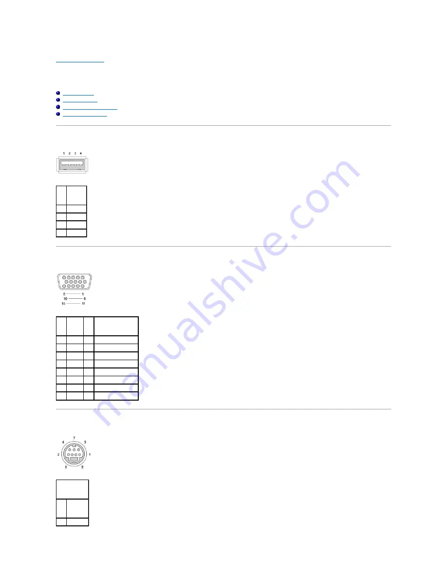


USB Connector 


Video Connector 


S-Video TV-Out Connector 


IEEE 1394 Connector 


USB Connector  


Video Connector  


S-Video TV-Out Connector  


Pin 


Signal 

USB5V+ 

USBP


USBP+ 

GND 


Pin 


Signal 


Pin 


Signal 

CRT_R  9 

5V+ 

CRT_G  10  GND 

CRT_B  11  MONITOR_DETECT


NC 

12  DDC_DATA 

GND 

13  CRT_HS 

GND 

14  CRT_VS 

GND 

15  DDC_CLK 

GND 


S-Video 


Pin


Signal


GND 

Содержание Latitude D520

Страница 1: ...rosoft Corporation Other trademarks and trade names may be used in this document to refer to either the entities claiming the marks and names or their products Dell Inc disclaims any proprietary interest in trademarks and trade names other than its own Model PP17L March 2006 Rev A00 Before You Begin System Components Media Bay Hard Drive Memory Module s Modem Mini Card Internal Card With Bluetooth...

Страница 2: ...ter from potential damage and to help ensure your own personal safety 1 Ensure that the work surface is flat and clean to prevent the computer cover from being scratched 2 Turn off your computer see Turning Off Your Computer 3 Disconnect any telephone or network cables from the computer NOTICE To avoid losing data save and close any open files and exit any open programs before you turn off your co...

Страница 3: ...tery from the battery bay 7 Turn the computer top side up Computer Orientation Screw Identification When you are removing and replacing components print the screw identification chart as a tool to lay out and keep track of the screws The chart provides the number of screws and their sizes NOTICE To help prevent damage to the system board remove the main battery before working inside the computer 1...

Страница 4: ...e 2 each Modem 1 each Keyboard 2 each Display Assembly 4 each Display Bezel 6 each under rubber display bumpers Display Panel 8 each Display Latch 1 each Palm Rest 14 each bottom side Palm Rest 4 each top side Speakers 1 each Fan 2 each System Board 2 each ...

Страница 5: ...le connector out of the system board connector 4 Pull the cable to remove the card from the computer Back to Contents Page CAUTION Before performing the following procedures read the safety instructions in your Product Information Guide NOTICE To avoid electrostatic discharge ground yourself by using a wrist grounding strap or by periodically touching a connector on the back panel of the computer ...

Страница 6: ... the card by pushing the metal securing tab away from the card until the card pops up slightly CAUTION Before you begin the following procedure follow the safety instructions in the Product Information Guide NOTICE To prevent damage to the system board remove the main battery before you service the computer NOTE If you ordered a WLAN card with your computer the card is already installed NOTE If yo...

Страница 7: ...age 1 WLAN card 2 metal securing tabs 2 NOTICE The connectors are keyed to ensure correct insertion If you feel resistance check the connectors and realign the card NOTE Do not insert a Mobile Broadband WWAN network card into the WLAN card connector NOTE The WLAN card may have two or three antenna connectors depending on the type of card you ordered NOTICE To avoid damaging the WLAN card never pla...

Страница 8: ...insert it at a 30 degree angle under the clip with the positive identified by a plus symbol side up and then push it into place Back to Contents Page CAUTION Before performing the following procedures follow the safety instructions in your Product Information Guide NOTICE To avoid electrostatic discharge ground yourself by using a wrist grounding strap or by periodically touching a connector on th...

Страница 9: ...y Dell is not covered by your warranty NOTICE Unless otherwise noted each procedure in this document assumes that a part can be replaced by performing the removal procedure in reverse order 1 display assembly 2 hinge cover 3 keyboard 4 palm rest with touch pad 5 processor 6 optical drive 7 speaker assembly 8 computer base 9 main battery 10 hard drive 11 system board assembly 12 fan 13 processor th...

Страница 10: ...n the substrate on which the die is mounted while turning the cam screw to prevent intermittent contact between the cam screw and processor NOTICE To avoid damage to the processor hold the screwdriver so that it is perpendicular to the processor when turning the cam screw NOTICE To help prevent damage to the system board remove the main battery see Before Working Inside Your Computer before workin...

Страница 11: ...beginning with step 4 Back to Contents Page NOTICE A processor module that is not properly seated can result in an intermittent connection or permanent damage to the processor and ZIF socket NOTE If a new microprocessor is installed you will receive one of the following a new thermal cooling assembly which will include an affixed thermal pad or you will receive a new thermal pad along with a tech ...

Страница 12: ...ng the Processor Thermal Cooling Assembly 1 Place the processor thermal cooling assembly over the processor CAUTION Before you begin the following procedure follow the safety instructions in the Product Information Guide NOTICE To avoid electrostatic discharge ground yourself by using a wrist grounding strap or by periodically touching an unpainted metal surface such as the back panel on the compu...

Страница 13: ...2 Tighten the six captive screws labeled 1 through 6 in consecutive order Back to Contents Page ...

Страница 14: ...old antenna connectors on each connector and gently pulling them apart 8 Remove the four M2 5 x 5 mm screws from the display and remove the display from the computer Replacing the Display Assembly CAUTION Before you begin the following procedure follow the safety instructions in the Product Information Guide NOTICE To avoid electrostatic discharge ground yourself by using a wrist grounding strap o...

Страница 15: ...ing at any corner use your fingers to gently snap the bezel into place to secure it to the display panel 2 Replace the six M2 x 5 mm screws around the display bezel NOTICE Ensure the antenna cables are not twisted and that they are lying flat in the antenna cable clip CAUTION Before you begin the following procedure follow the safety instructions in the Product Information Guide NOTICE To avoid el...

Страница 16: ...l tab to disconnect the bottom flex cable connector from the inverter connector CAUTION Before you begin the following procedure follow the safety instructions in the Product Information Guide NOTICE To avoid electrostatic discharge ground yourself by using a wrist grounding strap or by touching an unpainted metal surface on the computer NOTICE To help prevent damage to the system board you must r...

Страница 17: ...e display support bracket to the top cover 6 Lift the display support bracket out of the top cover and then remove the display latch 4 inverter connector NOTE The eight screw locations are numbered Replace the screws in sequential order CAUTION Before you begin the following procedure follow the safety instructions in the Product Information Guide NOTICE To avoid electrostatic discharge ground you...

Страница 18: ...Replacing the Display Latch 1 Align the latch with the posts on the display back and set into place 2 Replace the support bracket and replace the M2 x 4 mm screw Back to Contents Page ...

Страница 19: ...TION Before you begin the following procedure follow the safety instructions in the Product Information Guide NOTICE To avoid electrostatic discharge ground yourself by using a wrist grounding strap or by periodically touching an unpainted metal surface such as the back panel on the computer NOTICE To help prevent damage to the system board remove the main battery see Before Working Inside Your Co...

Страница 20: ...and f to reset the computer defaults 5 Press Esc select Save Exit and press Enter to save configuration changes 6 Remove the flash BIOS update program CD from the drive and restart the computer Back to Contents Page NOTICE Plug the AC adapter into a known good power source to prevent a loss of power Failure to do so may cause system damage NOTE If you use a BIOS update program CD to flash the BIOS...

Страница 21: ...ser s Guide CAUTION If you remove the hard drive from the computer when the drive is hot do not touch the metal housing of the hard drive CAUTION Before you begin the following procedure follow the safety instructions in the Product Information Guide NOTICE To prevent data loss turn off your computer before removing the hard drive Do not remove the hard drive while the computer is on in standby mo...

Страница 22: ...ing a Hard Drive to Dell Return your old hard drive to Dell in its original or comparable foam packaging Otherwise the hard drive may be damaged in transit Back to Contents Page 1 hard drive 2 foam packaging ...

Страница 23: ...h the display open all the way 180 degrees so that it lies flat against the work surface snap the cover back into place starting from left to right Back to Contents Page CAUTION Before you begin the following procedure follow the safety instructions in the Product Information Guide NOTICE To avoid electrostatic discharge ground yourself by using a wrist grounding strap or by periodically touching ...

Страница 24: ...ront edge of the keyboard into the palm rest and lay the keyboard down on the palm rest 3 Replace the two M2 5 x 5 mm screws at the top of the keyboard 4 Replace the hinge cover CAUTION Before you begin any of the procedures in this section follow the safety instructions in the Product Information Guide NOTICE To avoid electrostatic discharge ground yourself by using a wrist grounding strap or by ...

Страница 25: ...Back to Contents Page ...

Страница 26: ...k to Contents Page CAUTION Before you begin the following procedure follow the safety instructions in the Product Information Guide NOTICE To avoid electrostatic discharge ground yourself by using a wrist grounding strap or by periodically touching an unpainted metal surface such as the back panel on the computer NOTICE To help prevent damage to the system board remove the main battery see Before ...

Страница 27: ...e down 4 If present remove the M2 x 3 mm device security screw from the bottom of the computer 5 Press in the device latch release and pull the drive out of the media bay To replace the drive into the media bay push the new device into the bay until it clicks then replace the M2 x 3 mm security screw if present Back to Contents Page NOTE If the device security screw is not present you can remove a...

Страница 28: ...edures in Before You Begin 2 Remove the hinge cover see Hinge Cover 3 Remove the keyboard see Keyboard 4 Ground yourself by touching one of the metal connectors on the back of the computer 5 If you are replacing a memory module remove the existing module a Use your fingertips to carefully spread apart the securing clips on each end of the memory module connector until the module pops up b Remove t...

Страница 29: ...ts the additional memory and automatically updates the system configuration information To confirm the amount of memory installed in the computer click Start click Help and Support and then click Dell System Information DIMM B 1 Follow the procedures in Before You Begin 2 Turn the computer upside down loosen the captive screw on the cover and then remove the cover 3 If you are replacing a memory m...

Страница 30: ...ditional memory and automatically updates the system configuration information To confirm the amount of memory installed in the computer click Start click Help and Support and then click Dell System Information Back to Contents Page NOTICE If you need to install memory modules in two connectors install a memory module in the connector labeled DIMMA before you install a module in the connector labe...

Страница 31: ...ector on the system board CAUTION Before you begin the following procedure follow the safety instructions in the Product Information Guide NOTICE To avoid electrostatic discharge ground yourself by using a wrist grounding strap or by periodically touching an unpainted metal surface such as the back panel on the computer NOTICE To help prevent damage to the system board you must remove the main bat...

Страница 32: ...onnect the modem to the system board Align the connector on the bottom of the modem with the modem connector on the system board and press down on the right side of the modem 3 Replace the M2 x 3 mm screw Back to Contents Page NOTICE Ensure that the modem cable is routed correctly when you replace the modem ...

Страница 33: ... M2 5 x 8 mm screws from the bottom of the computer 8 Turn the computer top side up and remove the four M2 5 x 5 mm screws labeled P from the top of the palm rest CAUTION Before you begin the following procedure follow the safety instructions in the Product Information Guide NOTICE To avoid electrostatic discharge ground yourself by using a wrist grounding strap or by periodically touching an unpa...

Страница 34: ...four M2 5 x 5 mm screws on the top of the palm rest 4 Turn the computer upside down and replace the 14 M2 5 x 8 mm screws on the bottom of the computer Back to Contents Page 1 M2 5 x 5 mm screws 4 1 touch pad connector 2 tab CAUTION Before you begin the following procedure follow the safety instructions in the Product Information Guide NOTICE To avoid electrostatic discharge ground yourself by usi...

Страница 35: ...ector S Video TV Out Connector IEEE 1394 Connector USB Connector Video Connector S Video TV Out Connector Pin Signal 1 USB5V 2 USBP 3 USBP 4 GND Pin Signal Pin Signal 1 CRT_R 9 5V 2 CRT_G 10 GND 3 CRT_B 11 MONITOR_DETECT 4 NC 12 DDC_DATA 5 GND 13 CRT_HS 6 GND 14 CRT_VS 7 GND 15 DDC_CLK 8 GND S Video Pin Signal 1 GND ...

Страница 36: ...IEEE 1394 Connector Back to Contents Page 2 GND 3 DLUMA L 4 DCRMA L Composite Video Pin Signal 5 NC 6 DCMPS L 7 GND Pin Signal 1 TPB 2 TPB 3 TPA 4 TPA ...

Страница 37: ...u begin the following procedure follow the safety instructions in the Product Information Guide NOTICE To avoid electrostatic discharge ground yourself by using a wrist grounding strap or by periodically touching an unpainted metal surface such as the back panel on the computer NOTICE To help prevent damage to the system board remove the main battery see Before Working Inside Your Computer before ...

Страница 38: ...2 Replace the M2 5 x 5 mm screw that secures the speaker assembly in place Back to Contents Page ...

Страница 39: ...ving the Keyboard 9 Remove the display assembly see Removing the Display Assembly 10 Remove the processor thermal cooling assembly see Removing the Processor Thermal Cooling Assembly 11 Remove the processor see Removing the Processor Module 12 Remove the palm rest see Removing the Palm Rest 13 Remove the speaker assembly see Removing the Speaker Assembly 14 Remove the two M2 5 x 5 mm screws labele...

Страница 40: ... computer facing you grasp the upper right corner of the system board assembly and lift it slightly slowly easing the connectors out of their access holes on the back and side of the computer base b Pull the system board assembly away from you toward the front of the computer to remove the system board assembly 1 M2 5 x 5 mm screws 2 1 M2 x 3 mm screws labeled B 4 1 system board assembly ...

Страница 41: ...n 4 Enter the system setup program to update the BIOS on the new system board with the computer Service Tag Back to Contents Page NOTICE Before turning on the computer replace all screws and ensure that no stray screws remain inside the computer Failure to do so may result in damage to the computer NOTE If you use a BIOS update program CD to flash the BIOS press F12 before inserting the CD so that...

Страница 42: ...itude are trademarks of Dell Inc Bluetooth is a registered trademark owned by Bluetooth SIG Inc and is used by Dell under license Microsoft and Windows are registered trademarks of Microsoft Corporation Other trademarks and trade names may be used in this document to refer to either the entities claiming the marks and names or their products Dell Inc disclaims any proprietary interest in trademark...

Отзывы: