background image

Pași

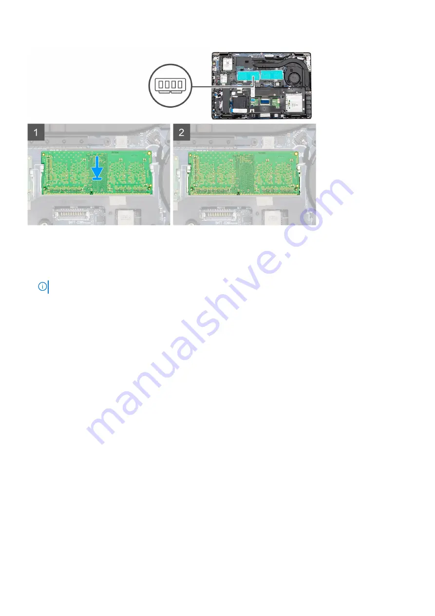
1. Align the notch on the memory module with the tab on the memory module slot.
2. Slide the memory module firmly into the slot at an angle.
3. Press the memory module down until it clicks into place.

NOTIFICARE

: If you do not hear the click, remove the memory module and reinstall it.

Pașii următori

1. Install the 

battery

.

2. Install the 

base cover

.

3. Follow the procedure in 

After working inside your computer

.

Unitate SSD

Removing the M.2 2280 SATA SSD

Cerințe preliminare

1. Follow the procedure in 

Before working inside your computer

.

2. Remove the 

base cover

.

3. Remove the 

battery

.

Despre această sarcină

The figure indicates the location of the SATA M.2 2280 SSD and provides a visual representation of the removal procedure.

24

Dezasamblarea și reasamblarea

Содержание Latitude 5411

Страница 1: ...Dell Latitude 5411 Service Manual Reglementare de Model P98G Reglementare de Tip P98G008 ...

Страница 2: ... pierdere de date şi vă arată cum să evitaţi problema AVERTISMENT Un AVERTISMENT indică un pericol potenţial de deteriorare a bunurilor de vătămare corporală sau de deces 2020 Dell Inc sau filialele sale Toate drepturile rezervate Dell EMC şi alte mărci comerciale sunt mărci comerciale ale Dell Inc sau ale filialelor sale Alte mărci comerciale pot fi mărci comerciale deţinute de proprietarii respe...

Страница 3: ...y 17 Installing the battery 17 placa WLAN 18 Removing the WLAN card 18 Installing the WLAN card 19 WWAN card 20 Removing the WWAN card 20 Installing the WWAN card 21 Modulele de memorie 22 Removing the memory module 22 Installing the memory module 23 Unitate SSD 24 Removing the M 2 2280 SATA SSD 24 Installing the SATA M 2 2280 SSD 25 Cadrul interior 26 Removing the inner frame 26 Installing the in...

Страница 4: ...button with fingerprint reader 59 Removing the power button with fingerprint reader 60 Capacele balamalelor 61 Removing the hinge caps 61 Installing the hinge caps 62 Ansamblul capacului din spate al afişajului 63 Replacing the display back cover 63 Balamalele afişajului 64 Removing display hinge 64 Installing display hinge 65 Cablul afişajului eDP 66 Removing display cable 66 Installing display c...

Страница 5: ... Logs Jurnale de sistem 96 Actualizarea BIOS în Windows 96 Actualizarea BIOS pe sistemele cu BitLocker activat 97 Actualizarea sistemului BIOS cu un dispozitiv de stocare USB 97 Parola de sistem și de configurare 98 Atribuirea unei parole de configurare a sistemului 98 Ștergerea sau modificarea unei parole de configurare a sistemului existente 99 4 Depanare 100 Diagnosticarea prin evaluarea îmbună...

Страница 6: ...autorizate de către Dell nu sunt acoperite de garanția dvs Citiți și respectați instrucțiunile de siguranță incluse în pachetul produsului AVERTIZARE Pentru a evita descărcarea electrostatică conectați vă la împământare utilizând o brățară antistatică sau atingând periodic o suprafață metalică nevopsită în timp ce atingeți un conector de pe partea din spate a computerului AVERTIZARE Manevrați comp...

Страница 7: ...nerea butonului de alimentare timp de 15 secunde ar trebui să descarce energia reziduală din placa de sistem Echipotențializarea Echipotențializarea este o metodă de a conecta două sau mai multe conductoare electrice la același potențial Acest lucru poate fi realizat utilizând un echipament de reparații pe teren ESD Când conectați un fir de echipotențializare asigurați vă că este conectat la metal...

Страница 8: ...oscută sub numele de legătură Utilizaţi numai kituri de service pe teren cu bandă de mână covoraş şi cablu de legătură Nu utilizaţi niciodată benzi de mână wireless Reţineţi întotdeauna că firele interne ale unei benzi de mână sunt expuse la deteriorări din cauza uzurii şi trebuie verificate cu regularitate cu ajutorul unui tester pentru benzi de mână pentru a evita deteriorarea accidentală a comp...

Страница 9: ...e piesele izolatoare în timpul intervenţiei de service precum şi să utilizeze recipiente antistatice pentru transportul componentelor sensibile După efectuarea lucrărilor în interiorul computerului Despre această sarcină După finalizarea oricărei proceduri de înlocuire asigurați vă că ați conectat dispozitivele externe plăcile și cablurile înainte de a porni computerul Pași 1 Conectați cablurile d...

Страница 10: ...Screw List The following table shows the screw list and the images for different components Tabel 1 Screw Size List Component Screw type Quantity Image Base cover M2 5x6 captive screws M2 5X8 captive screws NOTIFICARE Screws are part of the base cover 5 3 Battery M2x6 captive screw 1 WLAN M2x3 1 WWAN M2x3 1 DC In M2x5 2 SSD M2x3 1 HDD assembly M3x3 4 HDD bracket M2X2 7 4 Inner frame M2x5 M2x3 6 6 ...

Страница 11: ...m board 2 screws holding fan assy to the system board 1 screw holding fan to the heatsink System board M2x3 2 Keyboard M2x2 5 18 Keyboard support bracket M2x2 6 Power button with fingerprint reader M2x2 2 Display assembly M2x3 M2 5x5 2 4 Display panel M2 5x3 2 Hinge caps M2x3 2 Display Hinges M2 5x3 4 SIM cover For models shipped without the WWAN card and antennae 1 Remove the base cover from the ...

Страница 12: ...base cover Cerințe preliminare 1 Follow the procedure in Before working inside your computer NOTIFICARE Remove the SIM cover Despre această sarcină The figure indicates the location of the base cover and provides a visual representation of the removal procedure 12 Dezasamblarea și reasamblarea ...

Страница 13: ...Dezasamblarea și reasamblarea 13 ...

Страница 14: ...ound 3 Lift the base cover away from the computer Installing the base cover Cerințe preliminare If you are replacing a component remove the existing component before performing the installation procedure Despre această sarcină The figure indicates the location of the base cover and provides a visual representation of the installation procedure 14 Dezasamblarea și reasamblarea ...

Страница 15: ...Dezasamblarea și reasamblarea 15 ...

Страница 16: ... când manevrați baterii litiu ion Descărcați bateria cât de mult posibil înainte de a o scoate din sistem Acest lucru poate fi realizat deconectând adaptorul de c a de la sistem pentru a permite bateriei să se descarce Nu zdrobiți nu aruncați pe jos nu deformați și nu penetrați bateria cu obiecte străine Nu expuneți bateria la temperaturi înalte și nu dezasamblați acumulatorii și elementele Nu apl...

Страница 17: ...riginale de la www dell com sau parteneri și revânzători autorizați Dell Removing the battery Cerințe preliminare 1 Follow the procedure in Before working inside your computer 2 Remove the base cover Despre această sarcină The figure indicates the location of the battery and provides a visual representation of the removal procedure Pași 1 Disconnect the battery cable from the system board 2 Remove...

Страница 18: ...tery to the palmrest 3 Connect the battery cable to the connector on the system board Pașii următori 1 Install the base cover 2 Follow the procedure in After working inside your computer placa WLAN Removing the WLAN card Cerințe preliminare 1 Follow the procedure in Before working inside your computer 2 Remove the base cover 3 Remove the battery Despre această sarcină The figure indicates the loca...

Страница 19: ... module 4 Remove the WLAN card out of the computer Installing the WLAN card Cerințe preliminare If you are replacing a component remove the existing component before performing the installation procedure Despre această sarcină The figure indicates the location of the WLAN card and provides a visual representation of the installation procedure Dezasamblarea și reasamblarea 19 ...

Страница 20: ...WLAN card and replace the single M2x3 screw to secure the bracket to the computer Pașii următori 1 Install the battery 2 Install the base cover 3 Follow the procedure in After working inside your computer WWAN card Removing the WWAN card Cerințe preliminare 1 Follow the procedure in Before working inside your computer 2 Remove the base cover 3 Remove the battery 20 Dezasamblarea și reasamblarea ...

Страница 21: ...cket from the computer 3 Disconnect the WWAN antenna cables from the WWAN module 4 Remove the WWAN card out of the computer Installing the WWAN card Cerințe preliminare If you are replacing a component remove the existing component before performing the installation procedure Despre această sarcină The figure indicates the location of the WWAN card and provides a visual representation of the insta...

Страница 22: ...rd and replace the single M2x3 screw to secure the bracket to the computer Pașii următori 1 Install the battery 2 Install the base cover 3 Follow the procedure in After working inside your computer Modulele de memorie Removing the memory module Cerințe preliminare 1 Follow the procedure in Before working inside your computer 2 Remove the base cover 3 Remove the battery 22 Dezasamblarea și reasambl...

Страница 23: ...memory module pops up 2 Slide and remove the memory module from the memory module slot on the system board Installing the memory module Cerințe preliminare If you are replacing a component remove the existing component before performing the installation procedure Despre această sarcină The figure indicates the location of the memory module and provides a visual representation of the installation p...

Страница 24: ...all it Pașii următori 1 Install the battery 2 Install the base cover 3 Follow the procedure in After working inside your computer Unitate SSD Removing the M 2 2280 SATA SSD Cerințe preliminare 1 Follow the procedure in Before working inside your computer 2 Remove the base cover 3 Remove the battery Despre această sarcină The figure indicates the location of the SATA M 2 2280 SSD and provides a vis...

Страница 25: ...SD module out from the computer Installing the SATA M 2 2280 SSD Cerințe preliminare If you are replacing a component remove the existing component before performing the installation procedure Despre această sarcină The figure indicates the location of the SATA M 2 2280 SSD and provides a visual representation of the installation procedure Dezasamblarea și reasamblarea 25 ...

Страница 26: ...ow the procedure in After working inside your computer Cadrul interior Removing the inner frame Cerințe preliminare 1 Follow the procedure in Before working inside your computer 2 Remove the base cover 3 Remove the battery 4 Remove the 2280 SATA SSD 5 Remove the WLAN card 6 Remove the WWAN card Despre această sarcină The figure indicates the location of the inner frame and provides a visual repres...

Страница 27: ...e to the computer 4 Lift the inner frame out of the computer Installing the inner frame Cerințe preliminare If you are replacing a component remove the existing component before performing the installation procedure Despre această sarcină The figure indicates the location of the inner frame and provides a visual representation of the installation procedure Dezasamblarea și reasamblarea 27 ...

Страница 28: ...rame into the slot on your computer 2 Replace the six M2x5 and six M2x3 screws to secure the inner frame to the computer 3 Route the WWAN and WLAN antenna cables through the retention clips on the frame 28 Dezasamblarea și reasamblarea ...

Страница 29: ...ve Cerințe preliminare 1 Follow the procedure in Before working inside your computer 2 Remove the base cover 3 Remove the battery Despre această sarcină The figure indicates the location of the HDD and provides a visual representation of the removal procedure Pași 1 Locate the HDD on your computer 2 Disconnect the HDD cable from the system board 3 Remove the four M2x2 7 screws that secure the HDD ...

Страница 30: ...our computer 2 Align and install the HDD into the computer 3 Install the four M2x2 7 screws that secure the HDD to the computer 4 Connect the HDD cable on to the connector on the system board Pașii următori 1 Install the battery 2 Install the base cover 3 Follow the procedure in After working inside your computer Heatsink assembly UMA Removing the heatsink assembly UMA Cerințe preliminare 1 Follow...

Страница 31: ...Despre această sarcină The figure indicates the location of the heatsink and provides a visual representation of the removal procedure Dezasamblarea și reasamblarea 31 ...

Страница 32: ...mbly out of the computer 5 Remove the single M2x3 screw that secures the heatsink fan to the heatsink 6 Lift the heatsink fan away from the heatsink Installing the heatsink assembly UMA Cerințe preliminare If you are replacing a component remove the existing component before performing the installation procedure Despre această sarcină The figure indicates the location of the heatsink and provides ...

Страница 33: ...Dezasamblarea și reasamblarea 33 ...

Страница 34: ...ce the heatsink assembly into the slot of your computer 5 Replace the six M2x3 screws to secure the heatsink assembly to the system board NOTIFICARE Install the screws as per the callout on the heatsink 6 Connect the heatsink fan cable to the connector on the system board Pașii următori 1 Install the battery 2 Install the base cover 3 Follow the procedure in After working inside your computer 34 D...

Страница 35: ...ery 4 Remove the inner frame Despre această sarcină The figure indicates the location of the Heatsink and provides a visual representation of the removal procedure Pași 1 Locate the heatsink on your computer 2 Disconnect the fan cable from the connector on the system board 3 Remove the seven M2x3 screws that secure the heatsink assembly to the system board Dezasamblarea și reasamblarea 35 ...

Страница 36: ...crete Cerințe preliminare If you are replacing a component remove the existing component before performing the installation procedure Despre această sarcină The figure indicates the location of the heatsink and provides a visual representation of the installation procedure Pași 1 Align the screw hole on the heatsink with the screw hole on the heatsink fan 2 Replace the single M2x3 screw to secure ...

Страница 37: ...the battery 3 Install the base cover 4 Follow the procedure in After working inside your computer Portul de intrare c c Removing the DC in Cerințe preliminare 1 Follow the procedure in Before working inside your computer 2 Remove the base cover 3 Remove the battery 4 Remove the heatsink discrete Despre această sarcină The figure indicates the location of the DC in and provides a visual representat...

Страница 38: ... connector on the system board 5 Remove the DC in port from the computer Installing the DC in Cerințe preliminare If you are replacing a component remove the existing component before performing the installation procedure Despre această sarcină The figure indicates the location of the DC in and provides a visual representation of the installation procedure 38 Dezasamblarea și reasamblarea ...

Страница 39: ...lace the two screws M2x5 that secure the DC in metal bracket to the system board Pașii următori 1 Install the heatsink discrete 2 Install the battery 3 Install the base cover 4 Follow the procedure in After working inside your computer Bateria rotundă Removing the coin cell battery Cerințe preliminare 1 Follow the procedure in Before working inside your computer 2 Remove the base cover Dezasamblar...

Страница 40: ... battery cable from the connector on the system board 3 Lift the coin cell battery out of the computer Installing the coin cell battery Cerințe preliminare If you are replacing a component remove the existing component before performing the installation procedure Despre această sarcină The figure indicates the location of the coin cell and provides a visual representation of the installation proce...

Страница 41: ...e your computer Cititorul SmartCard Removing the smartcard reader board Cerințe preliminare 1 Follow the procedure in Before working inside your computer 2 Remove the base cover 3 Remove the battery 4 Remove the 2280 SATA SSD 5 Remove the WLAN card 6 Remove the WWAN card 7 Remove the inner frame Despre această sarcină The figure indicates the location of the smart card reader board and provides a ...

Страница 42: ... the three M2x3 screws that secure the smartcard reader board to the computer 6 Lift the smartcard reader module out of the computer Installing the smartcard reader board Cerințe preliminare If you are replacing a component remove the existing component before performing the installation procedure Despre această sarcină The figure indicates the location of the smartcard reader board and provides a...

Страница 43: ...he smartcard reader cable to the palmrest and connect the cable to the connector on the system board 5 Connect the touchpad button board cable to the connector on the system board Pașii următori 1 Install the inner frame 2 Install the WLAN card 3 Install the WWAN card 4 Install the 2280 SATA SSD 5 Install the battery 6 Install the base cover 7 Follow the procedure in After working inside your comp...

Страница 44: ...e Despre această sarcină The figure indicates the location of the touchpad button board and provides a visual representation of the removal procedure Pași 1 Locate the touchpad buttons board on your computer 2 Open the latch and disconnect the touchpad button board cable from the connector on the system board 3 Remove the two M2x3 screws that secure the touchpad button board to the palmrest 4 Lift...

Страница 45: ...on board slot on your computer 2 Align and place the touchpad button board into the slot on your computer 3 Replace the two M2x3 screws to secure the touchpad button board to the plamrest 4 Connect the touchpad button board cable to the connector on the system board and secure the latch Pașii următori 1 Install the inner frame 2 Install the WLAN card 3 Install the WWAN card 4 Install the 2280 SATA...

Страница 46: ...e base cover 3 Remove the battery 4 Remove the 2280 SATA SSD 5 Remove the WLAN card 6 Remove the WWAN card 7 Remove the inner frame 8 Remove the LED board Despre această sarcină The figure indicates the location of the speakers and provides a visual representation of the removal procedure 46 Dezasamblarea și reasamblarea ...

Страница 47: ...component remove the existing component before performing the installation procedure Despre această sarcină The figure indicates the location of the speakers and provides a visual representation of the installation procedure Pași 1 Locate the speakers slot on your computer 2 Align and place the speakers in the slot on your computer 3 Route the speaker cables through the retention clips on your com...

Страница 48: ...ur computer Panoul LED Removing the LED board Cerințe preliminare 1 Follow the procedure in Before working inside your computer 2 Remove the base cover 3 Remove the battery 4 Remove the 2280 SATA SSD 5 Remove the WLAN card 6 Remove the WWAN card 7 Remove the inner frame Despre această sarcină The figure indicates the location of the LED board and provides a visual representation of the removal pro...

Страница 49: ...rip 4 Remove the single M2x3 screw that secures the LED board to the computer 5 Lift the LED board out of the computer Installing the LED board Cerințe preliminare If you are replacing a component remove the existing component before performing the installation procedure Despre această sarcină The figure indicates the location of the LED board and provides a visual representation of the installati...

Страница 50: ...Adhere the LED board cable to the adhesive strip on the palmrest 5 Connect the LED board cable to the connector on the system board Pașii următori 1 Install the inner frame 2 Install the WLAN card 3 Install the WWAN card 4 Install the 2280 SATA SSD 5 Install the battery 6 Install the base cover 7 Follow the procedure in After working inside your computer 50 Dezasamblarea și reasamblarea ...

Страница 51: ... Remove the memory 6 Remove the WLAN card 7 Remove the WWAN card 8 Remove the inner frame 9 Remove the LED board 10 Remove the DC in 11 Remove the system board NOTIFICARE System board can be removed with heatsink attached Despre această sarcină The figure indicates the location of the keyboard and provides a visual representation of the removal procedure Dezasamblarea și reasamblarea 51 ...

Страница 52: ...ssembly from the palmrest 5 Flip the keyboard assembly 6 Remove the six M2x2 screws that secures the keyboard to the keyboard bracket 7 Remove the keyboard from the keyboard bracket Installing the keyboard Cerințe preliminare If you are replacing a component remove the existing component before performing the installation procedure Despre această sarcină The figure indicates the location of the ke...

Страница 53: ...e the keyboard to the keyboard bracket 2 Flip the keyboard assembly and align it to its slot on the palmrest 3 Press down on the lattice at the snap points in order to secure the keyboard assembly to the palmrest Dezasamblarea și reasamblarea 53 ...

Страница 54: ... the memory 6 Install the WLAN card 7 Install the WWAN card 8 Install the 2280 SATA SSD 9 Install the battery 10 Install the base cover 11 Follow the procedure in After working inside your computer Placa de sistem Removing the system board Cerințe preliminare 1 Follow the procedure in Before working inside your computer 2 Remove the base cover 3 Remove the battery 4 Remove the 2280 SATA SSD 5 Remo...

Страница 55: ...Dezasamblarea și reasamblarea 55 ...

Страница 56: ...isconnect the following cables a camera cable b speaker cable c LED board cable d fingerprint reader cable e keyboard cable 8 Remove the two M2x3 screws that secure the system board to the palmrest and keyboard assembly 9 Lift the system board off the palm rest and keyboard assembly Installing the system board Cerințe preliminare If you are replacing a component remove the existing component befor...

Страница 57: ...Dezasamblarea și reasamblarea 57 ...

Страница 58: ...on the computer 5 Place the finger print reader metal bracket over the fingerprint sensor 6 Replace the single M2x3 screw to secure the metal bracket to the computer 7 Connect the display cable to the connector on the system board 8 Adhere the tape that secures the display board to the system board 9 Replace the two M2x3 screws to secure the display metal bracket to the system board 10 Connect the...

Страница 59: ...replacing a component remove the existing component before performing the installation procedure Despre această sarcină The figure indicates the location of the power button with fingerprint and provides a visual representation of the installation procedure Pași 1 Locate the power button with fingerprint slot on your computer 2 Align and place the power button with fingerprint into the slot on you...

Страница 60: ...base cover 3 Remove the battery 4 Remove the 2280 SATA SSD 5 Remove the memory 6 Remove the WLAN card 7 Remove the WWAN card 8 Remove the inner frame 9 Remove the LED board 10 Remove the DC in 11 Remove the system board NOTIFICARE System board can be removed with heatsink attached Despre această sarcină The figure indicates the location of the power button with fingerprint reader and provides a vi...

Страница 61: ...Remove the display bezel Despre această sarcină The figure indicates the location of the hinge caps and provides a visual representation of the removal procedure Pași 1 Locate the hinge cap on the display back cover 2 Remove the two M2x3 screws that secure the hinge caps to the chassis 3 Pinch the hinge caps to release it from the ribs on the display back cover and then slide inwards to remove the...

Страница 62: ...ps and provides a visual representation of the installation procedure Pași 1 Place the hinge caps and slide outward on the display hinges 2 Replace the two M2x3 screws to secure the hinge caps to the display hinge Pașii următori 1 Install the display bezel 2 Install the display assembly 3 Install the battery 4 Install the base cover 5 Follow the procedure in After working inside your computer 62 D...

Страница 63: ...move the display panel 9 Remove the camera 10 Remove the display cable Despre această sarcină After performing the preceding steps you are left with the display back cover Pașii următori 1 Install the display cable 2 Install the camera 3 Install the display panel 4 Install the display hinges 5 Install the display hinge caps 6 Install the display bezel 7 Install the display assembly 8 Install the b...

Страница 64: ...ly 5 Remove the display bezel 6 Remove the display hinge caps 7 Remove the display panel Despre această sarcină The figure indicates the location of the camera and provides a visual representation of the removal procedure Pași 1 Remove the four M2 5x3 screws that secure the display hinge to the display assembly 2 Remove the display hinges from the display back cover 64 Dezasamblarea și reasamblare...

Страница 65: ...hinge on the display assembly 2 Replace the four M2 5x3 screws to secure the display hinge to the display assembly Pașii următori 1 Install the display panel 2 Install the display hinge caps 3 Install the display bezel 4 Install the display assembly 5 Install the battery 6 Install the base cover 7 Follow the procedure in After working inside your computer Dezasamblarea și reasamblarea 65 ...

Страница 66: ...the display bezel 6 Remove the display hinge caps 7 Remove the display panel 8 Remove the camera Despre această sarcină The figure indicates the location of the display cable and provides a visual representation of the removal procedure Pași Peel the conductive tape and unroute the display cable to release it from adhesive and lift the display cable from the display back cover 66 Dezasamblarea și ...

Страница 67: ...he display back cover 2 Adhere the conductive tape and route the display cable to the display back cover Pașii următori 1 Install the camera 2 Install the display panel 3 Install the display hinge caps 4 Install the display bezel 5 Install the display assembly 6 Install the battery 7 Install the base cover 8 Follow the procedure in After working inside your computer Dezasamblarea și reasamblarea 6...

Страница 68: ...r computer 2 Remove the base cover 3 Remove the battery 4 Remove the display assembly 5 Remove the display bezel 6 Remove the display hinge caps Despre această sarcină The figure indicates the location of the display panel and provides a visual representation of the removal procedure 68 Dezasamblarea și reasamblarea ...

Страница 69: ...Pași 1 Locate the display panel on the display back cover assembly Dezasamblarea și reasamblarea 69 ...

Страница 70: ...There is no need to separate the brackets from the display panel 5 Lift the latch and disconnect the display cable from the connector on the display panel Installing the display panel Cerințe preliminare If you are replacing a component remove the existing component before performing the installation procedure Despre această sarcină The figure indicates the location of the display panel and provid...

Страница 71: ...Dezasamblarea și reasamblarea 71 ...

Страница 72: ...y panel over the display back cover 4 Replace the two M2 5x3 screws that secure the display panel to the display assembly Pașii următori 1 Install the display hinge caps 2 Install the display bezel 3 Install the display assembly 4 Install the battery 5 Install the base cover 6 Follow the procedure in After working inside your computer 72 Dezasamblarea și reasamblarea ...

Страница 73: ...ly Despre această sarcină The figure indicates the location of the display bezel and provides a visual representation of the removal procedure Pași 1 Use a plastic scribe to pry open the bottom edge of the display bezel beginning from the recesses near the hinges 2 Work your way around the edges of the display bezel to release it from the display back cover 3 Remove the display bezel off the displ...

Страница 74: ...bezel and provides a visual representation of the installation procedure Pași Align the display bezel with the display back cover and antenna assembly and gently snap the display bezel into place Pașii următori 1 Install the display assembly 2 Install the WLAN card 3 Install the WWAN card 4 Install the battery 5 Install the base cover 6 Follow the procedure in After working inside your computer 74...

Страница 75: ...fore working inside your computer 2 Remove the base cover 3 Remove the battery 4 Remove the WLAN card 5 Remove the WWAN card Despre această sarcină The figure indicates the location of the display assembly and provides a visual representation of the removal procedure Dezasamblarea și reasamblarea 75 ...

Страница 76: ...76 Dezasamblarea și reasamblarea ...

Страница 77: ...e four M2 5x5 screws that secure the display hinges to the chassis of your computer 7 Open the display hinges at an angle of 90 degrees and slightly open the display 8 Remove the palm rest and keyboard assembly off the display assembly Installing the display assembly Cerințe preliminare If you are replacing a component remove the existing component before performing the installation procedure Desp...

Страница 78: ...78 Dezasamblarea și reasamblarea ...

Страница 79: ...Dezasamblarea și reasamblarea 79 ...

Страница 80: ...80 Dezasamblarea și reasamblarea ...

Страница 81: ... 6 Replace the two M2x3 screw to secure the display cable metal bracket to the system board 7 Connect the touchscreen cable to the connector on the system board 8 Replace the four M2 5x5 screws that secure the display hinge to the chassis of the computer 9 Route the WWAN cable and the WLAN cable through the retention clips provided Pașii următori 1 Install the WLAN card 2 Install the WWAN card 3 I...

Страница 82: ...e indicates the location of the camera and provides a visual representation of the removal procedure Pași 1 Peel the two conductive tape that secures the camera in place 2 Disconnect the camera cable from the connector on the camera module 3 Carefully pry and lift the camera module from the display back cover Installing camera Despre această sarcină The figure indicates the location of the camera ...

Страница 83: ...ttery 6 Install the base cover 7 Follow the procedure in After working inside your computer Ansamblul zonei de sprijin pentru mâini Replacing the palmrest assembly Cerințe preliminare 1 Follow the procedure in Before working inside your computer 2 Remove the base cover 3 Remove the battery 4 Remove the 2280 SATA SSD 5 Remove the memory 6 Remove the WLAN card 7 Remove the WWAN card 8 Remove the inn...

Страница 84: ...play assembly Despre această sarcină After performing the preceding steps you are left with the palmrest Palmrest without contactless smart card reader Palmrest with contactless smart card reader Pașii următori 1 Install the display assembly 84 Dezasamblarea și reasamblarea ...

Страница 85: ...heatsink attached 5 Install the DC in 6 Install the LED board 7 Install the inner frame 8 Install the memory 9 Install the WLAN card 10 Install the WWAN card 11 Install the 2280 SATA SSD 12 Install the battery 13 Install the base cover 14 Follow the procedure in After working inside your computer Dezasamblarea și reasamblarea 85 ...

Страница 86: ... încărcare Apăsați F12 când este afișată sigla Dell pentru a iniția un meniu de încărcare unică cu o listă a dispozitivelor de încărcare valabile pentru sistem De asemenea în acest meniu sunt incluse opțiunile de diagnosticare și de configurare BIOS Dispozitivele indicate în meniul de încărcare depind de cele instalate în sistem Acest meniu este util când încercați să încărcați pe un anumit dispoz...

Страница 87: ...ă secțiune pot să apară sau nu Opțiuni generale Tabel 2 Generalități Opțiune Descriere Informații sistem Afișează următoarele informații System Information Informații despre sistem afișează BIOS Version Versiune BIOS Service Tag Etichetă de service Asset Tag Etichetă de activ Ownership Tag Etichetă proprietar Manufacture Date Data fabricației Ownership Date Data achiziționării și Express Service C...

Страница 88: ...are a controlerului de hard disk integrat Disabled Dezactivat Controlerele SATA sunt ascunse AHCI Unitatea SATA este configurată pentru modul AHCI RAID ON Activare RAID unitatea SATA este configurată pentru a accepta modul RAID selectată în mod implicit Drives Vă permite să activați sau să dezactivați diverse unități integrate SATA 2 activată în mod implicit M 2 PCIe SSD 0 activată în mod implicit...

Страница 89: ...ele niveluri de iluminare Acest câmp are efect când iluminarea din fundal este activată Opțiunile sunt următoarele 5 s 10 s activată implicit 15 s 30 s 1 min 5 min 15 min Never Niciodată Keyboard Backlight Timeout on Battery Iluminarea din fundal a tastaturii se estompează în concordanță cu setările pentru baterie Caracteristica principală de iluminare a tastaturii nu este afectată Iluminarea tast...

Страница 90: ...te între 4 și 32 caractere Password Bypass Această opțiune vă permite să ocoliți mesajele de solicitare a parolei de sistem încărcare și a parolei hard diskului intern în timpul repornirii sistemului Disabled Dezactivat se solicită întotdeauna parola de sistem și cea a hard diskului intern când acestea sunt setate această opțiune este activată în mod implicit Reboot Bypass Ignorare la reîncărcare ...

Страница 91: ...ată o parolă de administrator Această opțiune nu este setată în mod implicit Master Password Lockout Vă permite să dezactivați suportul pentru parola principală Parolele de hard disk trebuie golite înainte ca setarea să poată fi modificată Această opțiune nu este setată în mod implicit SMM Security Mitigation Temperare securitate SMM Vă permite să activați sau să dezactivați protecțiile suplimenta...

Страница 92: ...e Intel SGX Enable Acest câmp vă permite să accesaţi un mediu securizat pentru executarea codurilor stocarea informaţiilor confidenţiale în contextul sistemului de operare principal Faceţi clic pe una dintre următoarele opţiuni Disabled Dezactivat Enabled Activat Software controlled Controlat prin software implicit Enclave Memory Size Această opţiune setează SGX Enclave Reserve Memory Size Dimensi...

Страница 93: ...lor Setare implicită Enabled Activat Auto On Time Vă permite să setați ora la care computerul trebuie să pornească automat Opțiunile sunt următoarele Disabled Dezactivat Every Day În fiecare zi Weekdays În zilele lucrătoare Select Days În anumite zile Setare implicită Disabled Dezactivat USB Wake Support Vă permite să activați dispozitive USB pentru a relua sistemul din starea de veghe NOTIFICARE ...

Страница 94: ...încărcare rapidă Primarily AC use Utilizare c a în principal Custom Particularizat Dacă este selectată opțiunea Custom Charge Încărcare particularizată puteți de asemenea să configurați opțiunile Custom Charge Start Pornire încărcare particularizată și Custom Charge Stop Oprire încărcare particularizată NOTIFICARE Este posibil ca nu toate modurile de încărcare să fie disponibile pentru toate bater...

Страница 95: ...y Activare tastă de acces rapid MEBx activată implicit Virtualization Support Suport virtualizare Opţiune Descriere Virtualization Acest câmp specifică dacă un instrument VMM Virtual Machine Monitor Monitor de maşini virtuale poate utiliza capacităţile hardware condiţionale oferite de tehnologia de virtualizare Intel Enable Intel Virtualization Technology Activare tehnologie de virtualizare Intel ...

Страница 96: ...că eMMC internă BIOS Recovery Acest câmp vă permite să recuperați sistemul din anumite stări de sistem BIOS deteriorat utilizând un fișier de recuperare de pe hard diskul principal al utilizatorului sau de pe o cheie USB externă BIOS Recovery from Hard Drive Recuperare BIOS de pe hard disk activată în mod implicit Always perform integrity check Se efectuează întotdeauna verificarea integrității de...

Страница 97: ...tările actualizate BIOS pe computer Urmați instrucțiunile de pe ecran Actualizarea BIOS pe sistemele cu BitLocker activat AVERTIZARE Dacă BitLocker nu este dezactivat înainte de actualizarea BIOS ului la următoarea reîncărcare a sistemului cheia BitLocker nu va fi recunoscută Vi se va solicita să introduceți cheia de recuperare pentru a continua iar sistemul va cere acest lucru la fiecare reîncărc...

Страница 98: ...uriza computerul AVERTIZARE Funcțiile parolei oferă un nivel de bază de securitate pentru datele de pe computer AVERTIZARE Oricine poate accesa datele stocate pe computer dacă acesta nu este blocat sau dacă este lăsat nesupravegheat NOTIFICARE Funcția parolei de sistem și de configurare este dezactivată Atribuirea unei parole de configurare a sistemului Cerințe preliminare Puteți atribui o System ...

Страница 99: ...a o parolă de sistem sau de configurare existentă dacă opțiunea Password Status Stare parolă este Locked Blocată Despre această sarcină Pentru a intra în configurarea de sistem apăsați F2 imediat după pornire sau reîncărcare Pași 1 În ecranul System BIOS BIOS sistem sau System Setup Configurare sistem selectați System Security Securitate sistem și apăsați Enter Ecranul System Security Securitate s...

Страница 100: ...nteți în fața terminalului computerului când sunt efectuate testele de diagnosticare Executarea diagnosticării ePSA Pași 1 Porniţi computerul 2 Când computerul se încarcă apăsați tasta F12 când apare sigla Dell 3 În ecranul meniului de încărcare selectați opțiunea Diagnostics Diagnosticare 4 Faceți clic pe săgeata din colțul din stânga jos Este afișată pagina de pornire a diagnosticării 5 Faceți c...

Страница 101: ...2 5 Memorie instalată nevalidă 2 6 Eroare placă de sistem sau chipset 2 7 Eroare afişaj 2 8 Defecțiune șină de alimentare LCD Remontați placa de sistem 3 1 Defecțiune baterie rotundă 3 2 Defecțiune PCI placă chip video 3 3 Nu s a găsit imaginea de recuperare 3 4 S a găsit imaginea de recuperare dar este nevalidă 3 5 Defecțiune șină de alimentare 3 6 Actualizarea sistemului BIOS incompletă 3 7 Eroa...

Страница 102: ...6 Porniți modemul 7 Porniţi computerul 102 Depanare ...

Страница 103: ...e şi prin telefon Disponibilitatea variază în funcţie de ţară şi produs şi este posibil ca anumite servicii să nu fie disponibile în zona dvs Pentru a contacta Dell referitor la probleme de vânzări asistenţă tehnică sau servicii pentru clienţi Pași 1 Accesaţi adresa Dell com support 2 Selectaţi categoria de asistenţă 3 Verificaţi ţara sau regiunea dvs în lista verticală Choose a Country Region Ale...
Отзывы: