background image

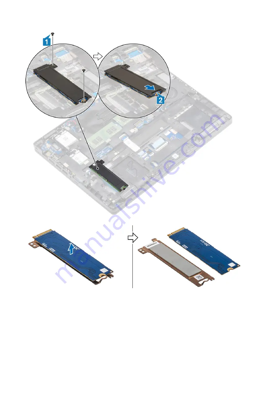
3. Lift the M.2 SSD away from the computer and remove the SSD of the SSD thermal plate

Installing the M.2 SSD

Steps

1. Place the M.2 SSD into the slot on the palmrest [1].
2. Align and place the SSD support bracket above the M.2 SSD [2].
3. Replace the two (M2x3) screws to secure the SSD support bracket to the palmrest [3].

Onderdelen verwijderen en plaatsen

35

Содержание Latitude 5400 Chrome

Страница 1: ...Dell Latitude 5400 Chrome Service Manual Regulatory Model P98G Regulatory Type P98G005 ...

Страница 2: ...l gegevensverlies aan en vertellen u hoe het probleem kan worden vermeden GEVAAR LET OP duidt het risico van schade aan eigendommen lichamelijk letsel of overlijden aan 2019 Dell Inc of zijn dochtermaatschappijen Alle rechten voorbehouden Dell EMC en andere handelsmerken zijn handelsmerken van Dell Inc of zijn dochterondernemingen Andere handelsmerken zijn mogelijk handelsmerken van hun respectiev...

Страница 3: ...emonteren en hermonteren 11 microSD kaart 11 Onderplaat 13 Batterij 18 WLAN kaart 22 WWAN kaart 24 Knoopbatterij 26 Geheugenmodules 28 Gelijkspanningsingangspoort 30 Solid state schijf 34 Beugel van Solid State schijf 36 Binnenframe 38 Touchpadknoppen 42 LED kaart 46 Luidsprekers 50 Warmteafleider 55 Systeemventilator 57 Moederbord 61 Toetsenbord 67 Toetsenbordbracket 71 Power button 72 Beeldscher...

Страница 4: ...gebruikte CROSH opdracht 112 Controleer de status van het laden van de batterij 112 Chromebook herstellen 119 Het herstellen van de Chromebook 119 Chromebook resetten 121 Ingebouwde zelftest voor lcd 124 Diagnostische LED lampjes 125 Diagnostiek 125 Validatiehulpprogramma s 130 4 Hulp verkrijgen en contact opnemen met Dell 137 4 Contents ...

Страница 5: ...che team voor service en ondersteuning Schade als gevolg van onderhoudswerkzaamheden die niet door Dell zijn goedgekeurd valt niet onder de garantie Lees de veiligheidsinstructies die bij het product zijn geleverd en leef deze na WAARSCHUWING Voorkom elektrostatische ontlading door uzelf te aarden met een aardingspolsbandje of door regelmatig zowel een ongeverfd metalen oppervlak als een connector...

Страница 6: ...and Dell producten met stand bystand moeten worden losgekoppeld voordat u de behuizing opent Systemen die zijn uitgerust met de stand bystand worden in wezen gevoed wanneer deze uit staan Door de interne voeding kan het systeem op afstand worden ingeschakeld Wake on LAN en onderbroken in een slaapstand en heeft andere geavanceerde functies voor energiebeheer Door ontkoppeling en het ingedrukt houd...

Страница 7: ...laatsen ESD gevoelige items zijn veilig in uw hand op de ESD mat in het systeem of in een zak Polsband en aardingssnoer De polsband en het aardingssnoer kunnen ofwel direct tussen uw pols en blank metaal op de hardware worden bevestigd als de ESD mat niet vereist is of worden verbonden met de antistatische mat om hardware te beschermen die tijdelijk op de mat is geplaatst De fysieke verbinding van...

Страница 8: ...ra hulpmiddelen of gebruik een mechanische hefinrichting 1 Zorg dat u stevig en in evenwicht staat Houd uw voeten uit elkaar voor een stabiele basis en richt uw tenen naar buiten 2 Span uw buikspieren aan De buikspieren ondersteunen uw rug bij het tillen waardoor de kracht van de last wordt gecompenseerd 3 Til met uw benen niet uw rug 4 Houd de last dicht bij uw lichaam Hoe dichter deze bij uw rug...

Страница 9: ...veilig opbergen Als het apparaat wordt ingeschakeld herhaalt u stappen 2 tot 4 Wanneer u het apparaat weer wilt gebruiken 1 Sluit het Chrome apparaat aan op een oplader en een voedingsbron zodat het apparaat uit de status voor het ontkoppelen van de batterij wordt gehaald Zet het apparaat aan 2 Maak verbinding met wifi en werk uw Chrome apparaat bij naar de laatste versie van het Chrome besturings...

Страница 10: ...oeven Deze tabel toont de schroeflijst en de afbeeldingen van de Dell Latitude 5300 2 in 1 Chrome voor verschillende onderdelen Tabel 1 Lijst met schroefmaten Onderdeel Type schroef Aantal Installatiekopie Onderplaat M2 5x6 5 borgschroeven OPMERKING Schroeven zijn onderdeel van de onderplaat 8 Batterij M2x5 borgschroeven 2 WWAN M2x3 1 WLAN M2x2 1 Steunbeugel van de SSD M2x3 2 SSD M2x2 grote schroe...

Страница 11: ...3 3 Moederbord M2 5x4 2 Toetsenbordondersteuningsbeug el M2x2 19 Toetsenbord M2x2 5 Demonteren en hermonteren microSD kaart Removing the microSD card Prerequisites 1 Follow the procedure in Before working inside your computer Steps 1 Push the microSD card to release it from the computer 1 2 Slide the microSD card out of the computer 2 Onderdelen verwijderen en plaatsen 11 ...

Страница 12: ...Installing the microSD card Steps 1 Align the microSD card to its slot on the computer 1 2 Slide the microSD card into the slot until it clicks into place 2 12 Onderdelen verwijderen en plaatsen ...

Страница 13: ...ing inside your computer Onderplaat Removing the base cover Prerequisites 1 Follow the procedure in before working with your computer 2 Remove the microSD card Steps 1 Loosen the eight captive screws 1 Onderdelen verwijderen en plaatsen 13 ...

Страница 14: ...2 Using a plastic scribe 1 pry the base cover from the top left corner and continue to work on the sides to open the base cover 2 14 Onderdelen verwijderen en plaatsen ...

Страница 15: ...3 Lift and remove the base cover away from the computer Installing the base cover Steps 1 Align and place the base cover on the computer Onderdelen verwijderen en plaatsen 15 ...

Страница 16: ...2 Press the edges and sides of the base cover until it snaps into place 16 Onderdelen verwijderen en plaatsen ...

Страница 17: ...3 Tighten the eight captive screws to secure the base cover to the computer Onderdelen verwijderen en plaatsen 17 ...

Страница 18: ...g dat er tijdens het onderhoud van dit product geen schroeven zoekraken of verloren gaan om te voorkomen dat de batterij en andere systeemonderdelen per ongeluk worden doorboord of schade oplopen Als de batterij vast komt te zitten in de computer als gevolg van zwellen moet u niet proberen deze los te maken omdat het doorboren buigen of pletten van een lithium ionbatterij gevaarlijk kan zijn Neem ...

Страница 19: ...3 Loosen the single captive screw that secures the battery to the palmrest 1 Slide the battery inward and lift the battery away from the palmrest Onderdelen verwijderen en plaatsen 19 ...

Страница 20: ...Installing the battery Steps 1 Align and slide the battery on the palmrest 1 2 Tighten the single captive screw to secure the battery to the palmrest 2 20 Onderdelen verwijderen en plaatsen ...

Страница 21: ...3 Connect the battery cable to the connector on the system board Onderdelen verwijderen en plaatsen 21 ...

Страница 22: ... computer 2 Remove the microSD card 3 Remove the base cover Steps 1 Remove the single M2x3 M2x3 screw that secures the WLAN card bracket to the system board 1 2 Remove the WLAN card bracket that secures the WLAN antenna cables 2 3 Disconnect the WLAN antenna cables from the connectors on the WLAN card 3 4 Slide and lift the WLAN card away from the connector on the system board 4 22 Onderdelen verw...

Страница 23: ... 1 Insert the WLAN card into the connector on the system board 1 2 Connect the WLAN antenna cables to the connectors on the WLAN card 2 3 Place the WLAN card bracket to secure the WLAN antenna cables to the WLAN card 3 4 Replace the single M2x3 screw to secure the WLAN card bracket to the WLAN card 4 Onderdelen verwijderen en plaatsen 23 ...

Страница 24: ...r 2 Remove the microSD card 3 Remove the base cover 4 Remove the battery Steps 1 Remove the single M2x3 screw that secures the WWAN card bracket to the system board 1 2 Remove the WWAN card bracket that secures the WWAN antenna cables 2 3 Disconnect the WWAN antenna cables from the connectors on the WWAN card 3 4 Slide and lift the WWAN card away from the connector on the system board 4 24 Onderde...

Страница 25: ... the WWAN card into the connector on the system board 1 2 Connect the WWAN antenna cables to the connectors on the WWAN card 2 3 Place the WWAN card bracket to secure the WWAN antenna cables to the WWAN card 3 4 Replace the single M2x3 screw to secure the WWAN card bracket to the WWAN card 4 Onderdelen verwijderen en plaatsen 25 ...

Страница 26: ...in before working with your computer 2 Remove the microSD card 3 Remove the base cover 4 Remove the battery 5 Remove the WWAN 6 Remove the WLAN 7 Remove the memory module 8 Remove the DC in port Steps 1 Turn the system board and disconnect the coin cell battery cable from the connector on the system board 2 Disconnect the coin cell battery cable from the connector on the system board 1 26 Onderdel...

Страница 27: ...ll battery Steps 1 Turn the system board and connect the coin cell battery cable to the connector on the system board 2 Place the coin cell on the system board 1 3 Connect the coin cell battery cable to the connector on the system board 2 Onderdelen verwijderen en plaatsen 27 ...

Страница 28: ...r working on your computer Geheugenmodules Removing the memory module Prerequisites 1 Follow the procedure in before working with your computer 2 Remove the microSD card 3 Remove the base cover 4 Remove the battery Steps 1 Pry the retention clips securing the memory module until the memory module pops up 1 2 Remove the memory module from the memory module slot 2 28 Onderdelen verwijderen en plaats...

Страница 29: ...e with the tab on the memory module slot 2 Slide the memory module firmly into the slot at an angle 1 3 Press the memory module down until the clips secure it 2 NOTE If you do not hear the click remove the memory module and reinstall it Onderdelen verwijderen en plaatsen 29 ...

Страница 30: ...angspoort Removing the DC in port Prerequisites 1 Follow the procedure in before working with your computer 2 Remove the microSD card 3 Remove the base cover 4 Remove the battery Steps 1 Remove the two M2x4 and M2x5 screws that secure the Type C bracket to the system board 1 Lift the Type C bracket away from the computer 2 30 Onderdelen verwijderen en plaatsen ...

Страница 31: ...2 Disconnect the DC in port cable from the connector on the system board and remove the DC in port from the computer 1 2 Onderdelen verwijderen en plaatsen 31 ...

Страница 32: ...Installing the DC in port Steps 1 Place the DC in port to its slot on the computer 1 2 Connect the DC in port cable to the connector on the system board 2 32 Onderdelen verwijderen en plaatsen ...

Страница 33: ...3 Place the Type C bracket on its slot on the computer 1 4 Replace the two M2x4 and M2x5 screws to secure the Type C bracket to the palmrest 2 Onderdelen verwijderen en plaatsen 33 ...

Страница 34: ...tes 1 Follow the procedure in before working with your computer 2 Remove the microSD card 3 Remove the base cover 4 Remove the battery Steps 1 Remove the two M2x3 screws that secures the SSD to the palmrest 1 2 Slightly turn and remove the SSD support bracket from the M 2 SSD slot 2 Remove the single M2x2 screw that secures the M 2 SSD to the palmrest 1 34 Onderdelen verwijderen en plaatsen ...

Страница 35: ...hermal plate Installing the M 2 SSD Steps 1 Place the M 2 SSD into the slot on the palmrest 1 2 Align and place the SSD support bracket above the M 2 SSD 2 3 Replace the two M2x3 screws to secure the SSD support bracket to the palmrest 3 Onderdelen verwijderen en plaatsen 35 ...

Страница 36: ...te schijf Removing the solid state drive bracket Prerequisites 1 Follow the procedure in before working with your computer 2 Remove the microSD card 3 Remove the base cover 4 Remove the battery Steps 1 Remove the single M2x3 screw that secures the bracket to the palmrest 1 2 Lift the SSD bracket of the slot on the palmrest 2 36 Onderdelen verwijderen en plaatsen ...

Страница 37: ... the solid state drive bracket Steps 1 Align the bracket and insert it into the slot on the palmrest 1 2 Replace the single M2x3 screw to secure the bracket to the palmrest 2 Onderdelen verwijderen en plaatsen 37 ...

Страница 38: ...ing the inner frame Prerequisites 1 Follow the procedure in before working with your computer 2 Remove the microSD card 3 Remove the base cover 4 Remove the battery 5 Remove the WWAN 6 Remove the WLAN 7 Remove the memory module 8 Remove the DC in port 9 Remove the Coin cell battery Steps 1 Unroute the WLAN antenna cables 38 Onderdelen verwijderen en plaatsen ...

Страница 39: ...screws that secure the inner frame to the system board 1 3 Remove the six M2x3 screws that secure the inner frame to the system chassis 2 4 Lift the inner frame away from the system chassis 3 Onderdelen verwijderen en plaatsen 39 ...

Страница 40: ...d place the inner frame on the system chassis 1 2 Replace the six M2x3 screws to secure the inner frame to the system chassis 2 3 Replace the three M2x5 screws to secure the inner frame to the system board 3 40 Onderdelen verwijderen en plaatsen ...

Страница 41: ...4 Reroute the WLAN antenna cables Onderdelen verwijderen en plaatsen 41 ...

Страница 42: ...oSD card 9 Follow the procedure in After working on your computer Touchpadknoppen Removing the touchpad button board Prerequisites 1 Follow the procedure in before working with your computer 2 Remove the microSD card 3 Remove the base cover 4 Remove the battery 5 Remove the WWAN 6 Remove the WLAN 7 Remove the memory module 8 Remove the DC in port 9 Remove the Coin cell battery 42 Onderdelen verwij...

Страница 43: ...rom the connector on the touchpad board 1 2 Peel out the speaker cable tapes securing the touchpad buttons 2 3 Remove the two M2x3 screws that secure the touchpad button bracket to the palmrest 1 4 Lift the touchpad button board bracket away from the computer 2 Onderdelen verwijderen en plaatsen 43 ...

Страница 44: ... touchpad button board Steps 1 Place the touchpad button board into the slot on the palmrest 1 2 Replace the two M2x3 screws to secure the touchpad button board to the palmrest 2 44 Onderdelen verwijderen en plaatsen ...

Страница 45: ...3 Adhere the speaker cable tapes securing the touchpad buttons 2 4 Open the latch and fix the touchpad button board cable to the connector on the touchpad board 1 Onderdelen verwijderen en plaatsen 45 ...

Страница 46: ...e cover 9 Install the microSD card 10 Follow the procedure in After working on your computer LED kaart Removing the LED board Prerequisites 1 Follow the procedure in before working with your computer 2 Remove the microSD card 3 Remove the base cover 4 Remove the battery 5 Remove the WWAN 6 Remove the WLAN 7 Remove the memory module 8 Remove the DC in port 46 Onderdelen verwijderen en plaatsen ...

Страница 47: ...USH daughter board 1 2 2 Disconnect the LED board cable from the connector on the system board 3 Unroute the LED board cable 2 4 Peel the grey adhesive tape that secures the LED board 2 5 Remove the single M2x2 5 screw that secures LED board to the palmrest 1 6 Lift the LED board away from the computer 2 Onderdelen verwijderen en plaatsen 47 ...

Страница 48: ...ED board Steps 1 Place the LED board and align the screw hole on the LED board with the screw hole on the palmrest 1 2 Replace the single M2x2 5 screw to secure the LED board to the palmrest 2 48 Onderdelen verwijderen en plaatsen ...

Страница 49: ...ED board cable to the connector on the system board and route the LED board cable 1 4 Connect and adhere the USH daughter board Flexible Flat Cable FFC from the USH daughter board Onderdelen verwijderen en plaatsen 49 ...

Страница 50: ... cover 9 Install the microSD card 10 Follow the procedure in After working on your computer Luidsprekers Removing the speakers Prerequisites 1 Follow the procedure in before working with your computer 2 Remove the microSD card 3 Remove the base cover 4 Remove the battery 5 Remove the WWAN 6 Remove the WLAN 7 Remove the memory module 8 Remove the DC in port 50 Onderdelen verwijderen en plaatsen ...

Страница 51: ...cable from the connector on the system board 1 2 Peel the adhesive tape that secures the speaker cable to the palmrest 2 3 Disconnect the touchpad cable from the connector on the daughter board 3 4 Peel the adhesive tapes and unroute the speaker cable Onderdelen verwijderen en plaatsen 51 ...

Страница 52: ...5 Lift and remove the speakers away from the palmrest 52 Onderdelen verwijderen en plaatsen ...

Страница 53: ...peakers Steps 1 Using the alignment posts and rubber grommets place the speakers in the slots on the palmrest Install Speakers 2 Route the speaker cable through the routing guides Onderdelen verwijderen en plaatsen 53 ...

Страница 54: ...3 Affix the adhesive tape to secure speaker cable to the palmrest 1 2 4 Connect the speaker cable to the connector on the system board 3 54 Onderdelen verwijderen en plaatsen ...

Страница 55: ...base cover 9 Install the microSD card 10 Follow the procedure in After working on your computer Warmteafleider Removing the heatsink assembly Prerequisites 1 Follow the procedure in before working with your computer 2 Remove the microSD card 3 Remove the base cover 4 Remove the battery 5 Remove the WWAN 6 Remove the WLAN 7 Remove the memory module 8 Remove the DC in port Onderdelen verwijderen en ...

Страница 56: ...atsink assembly to the system board 1 Installing the heatsink assembly Steps 1 Place the heatsink assembly on the system board and align the screw holes on the heatsink with the screw holes on the system board 1 2 In sequential order as indicated on the heatsink tighten the four M2x3 screws that secure the heatsink assembly to the system board 2 56 Onderdelen verwijderen en plaatsen ...

Страница 57: ...7 Install the battery 8 Install the base cover 9 Install the microSD card 10 Follow the procedure in After working on your computer Systeemventilator Removing the system fan Prerequisites 1 Follow the procedure in before working with your computer 2 Remove the microSD card 3 Remove the base cover 4 Remove the battery Onderdelen verwijderen en plaatsen 57 ...

Страница 58: ...emove the Coin cell battery 10 Remove the Inner frame Steps 1 Disconnect the system fan cable from the connector on the system board 2 Remove the two M2x5 screws that secure the system fan to the palmrest 1 3 Lift the system fan away from the computer 2 58 Onderdelen verwijderen en plaatsen ...

Страница 59: ...stem fan Steps 1 Place and align the screw holes on the system fan with the screw holes on to the palmrest 1 2 Replace the two M2x5 screws to secure the system fan to the palmrest 2 Onderdelen verwijderen en plaatsen 59 ...

Страница 60: ...3 Connect the system fan cable to the connector on the system board 60 Onderdelen verwijderen en plaatsen ...

Страница 61: ...cover 9 Install the microSD card 10 Follow the procedure in After working on your computer Moederbord Removing the system board Prerequisites 1 Follow the procedure in before working with your computer 2 Remove the microSD card 3 Remove the base cover 4 Remove the battery 5 Remove the WWAN 6 Remove the WLAN 7 Remove the memory module 8 Remove the DC in port Onderdelen verwijderen en plaatsen 61 ...

Страница 62: ...o the system board 2 3 Lift the eDP cable bracket from the system board 3 4 Disconnect the eDP cable from the system board 4 5 Disconnect the following cables a Speaker cable 2 b LED board cable 1 c touchpad cable 3 6 Remove the two M2 5x4 screws that secures the system board 1 7 Peel the adhesive tape and disconnect the cable from the connector on the system board 1 8 Disconnect the sensor board ...

Страница 63: ...9 Remove the two M2 5x4 screws that secures the system board to the palmrest 1 Onderdelen verwijderen en plaatsen 63 ...

Страница 64: ...Installing the system board Steps 1 Align and place the system board to the palmrest 1 2 Replace the two M2 5x4 screws to secure the system board to the palmrest 2 64 Onderdelen verwijderen en plaatsen ...

Страница 65: ...3 Connect the following cables a Speaker cable 2 b LED board cable 1 c touchpad cable 3 Onderdelen verwijderen en plaatsen 65 ...

Страница 66: ...stem board and adhere the adhesive tape 1 5 Replace the eDP cable bracket on the eDP cable connector on the system board 2 6 Replace the single M2x4 screw that secures the eDP cable bracket to the system board 3 4 66 Onderdelen verwijderen en plaatsen ...

Страница 67: ...mory module 7 Install the WLAN 8 Install the WWAN 9 Install the battery 10 Install the base cover 11 Install the microSD card 12 Follow the procedure in After working on your computer Toetsenbord Removing the keyboard Prerequisites 1 Follow the procedure in before working with your computer 2 Remove the microSD card Onderdelen verwijderen en plaatsen 67 ...

Страница 68: ...y Steps 1 Lift the latch and disconnect the backlit cable and the keyboard cable from the connectors on the touchpad 2 Remove the M2x2 5 screws that secure the keyboard to the palmrest 1 3 Remove the keyboard away from the computer 2 The touchpad FFC covers one of the screws that secure the keyboard assembly to the palmrest 68 Onderdelen verwijderen en plaatsen ...

Страница 69: ...Installing the keyboard Steps 1 Align and place the keyboard on the palmrest 1 2 Replace the 18 M2x2 5 screws to secure the keyboard to the palmrest 2 Onderdelen verwijderen en plaatsen 69 ...

Страница 70: ...3 Connect the backlit cable and the keyboard cable to the connectors on the touchpad 70 Onderdelen verwijderen en plaatsen ...

Страница 71: ... Install the base cover 8 Install the microSD card 9 Follow the procedure in After working on your computer Toetsenbordbracket Removing the keyboard bracket Prerequisites 1 Follow the procedure in before working with your computer 2 Remove the microSD card 3 Remove the base cover 4 Remove the battery 5 Remove the WWAN 6 Remove the WLAN 7 Remove the memory module 8 Remove the DC in port Onderdelen ...

Страница 72: ...he system board 3 Install the LED board 4 Install the speaker 5 Install the System fan 6 Install the Heatsink 7 Install the Inner frame 8 Install the coin cell battery 9 Install the DC in 10 Install the memory module 11 Install the WLAN 12 Install the WWAN 13 Install the battery 14 Install the base cover 15 Install the microSD card 16 Follow the procedure in After working on your computer Power bu...

Страница 73: ...t secure the power button with the fingerprint reader on the palmrest 1 2 Lift the power button with fingerprint reader board off the palmrest 2 Installing the power button Steps 1 Place the power button with fingerprint reader on the palmrest 1 2 Replace the two M2x3 screws that secure the power button with fingerprint reader on the palmrest 2 Onderdelen verwijderen en plaatsen 73 ...

Страница 74: ... 9 Install the DC in 10 Install the memory module 11 Install the WLAN 12 Install the WWAN 13 Install the battery 14 Install the base cover 15 Install the microSD card 16 Follow the procedure in After working on your computer Beeldschermassemblage Removing the display assembly Prerequisites 1 Follow the procedure in before working with your computer 2 Remove the microSD card 74 Onderdelen verwijder...

Страница 75: ...d 1 2 Remove the two M2x4 screws that secures the eDP cable bracket to the system board 2 3 Lift the eDP cable bracket from the system board 3 4 Disconnect and unroute the eDP cable 4 5 Open the display assembly to a 180 degree angle and flip over the system and then place the system on a flat surface Onderdelen verwijderen en plaatsen 75 ...

Страница 76: ...6 Remove the four M2 5x4 screws that secure the display assembly to the system chassis 1 7 Remove the display assembly from the system 2 76 Onderdelen verwijderen en plaatsen ...

Страница 77: ...aximum before replacing the display assembly on the palmrest and keyboard assembly Steps 1 Align and place the system chassis under the hinges of the display assembly 1 2 Replace the four M2 5x3 screws that secures the display assembly to the system chassis 2 Onderdelen verwijderen en plaatsen 77 ...

Страница 78: ...3 Seat the system chassis on the display assembly 78 Onderdelen verwijderen en plaatsen ...

Страница 79: ...dhere the adhesive tape 1 5 Reroute the eDP cable and connect it to the eDP connector 2 6 Place the eDP cable bracket on the system board 3 7 Replace the two M2x4 screws that secures the eDP cable bracket to the system board 4 Onderdelen verwijderen en plaatsen 79 ...

Страница 80: ...puter Montagekader van het beeldscherm Removing display bezel Prerequisites 1 Follow the procedure in before working with your computer 2 Remove the microSD card 3 Remove the base cover 4 Remove the battery 5 Remove the display assembly Steps 1 NOTE Display bezel cannot be reused after being removed 80 Onderdelen verwijderen en plaatsen ...

Страница 81: ...ong the outside edge of the display bezel using your hands or plastic scribes using a screw driver or other sharp objects may damage the display cover 2 Carefully pry open the inside edge of the display bezel and then pry open the inside edge of the left and right sides of the display bezel 2 3 Lift the display bezel from the display assembly Onderdelen verwijderen en plaatsen 81 ...

Страница 82: ...Installing the display bezel Steps Align the display bezel with the display assembly and then gently snap the display bezel into place 82 Onderdelen verwijderen en plaatsen ...

Страница 83: ...Onderdelen verwijderen en plaatsen 83 ...

Страница 84: ... the procedure in before working with your computer 2 Remove the microSD card 3 Remove the base cover 4 Remove the battery 5 Remove the WWAN 6 Remove the WLAN 7 Remove the Inner frame 8 Remove the display assembly 9 Remove the Display hinges Steps 1 Remove the M2 5x3 screws that secure the display panel to the display assembly 1 and lift to turn over the display panel to access the display cable 2...

Страница 85: ...res the display cable connector 2 4 Lift the latch and disconnect the display cable from the connector on the display panel Do not pull and release the Stretch SR Tapes from the display panel There is no need to separate the brackets from the display panel 3 4 Onderdelen verwijderen en plaatsen 85 ...

Страница 86: ...86 Onderdelen verwijderen en plaatsen ...

Страница 87: ...display cable connector 3 4 3 Adhere the conductive tape to secure the display cable connector LCD Panel comes with two L R brackets that needs to toe in first then secure two screws located at the base of the LCD panel 4 Replace the two M2 5x3 screws that secure the display panel to the display assembly Onderdelen verwijderen en plaatsen 87 ...

Страница 88: ... Install the WWAN 8 Install the Inner frame 9 Follow the procedure in After working on your computer Camera Removing camera Prerequisites 1 Follow the procedure in before working with your computer 2 Remove the microSD card 3 Remove the base cover 4 Remove the battery 5 Remove the WWAN 6 Remove the WLAN 7 Remove the Inner frame 88 Onderdelen verwijderen en plaatsen ...

Страница 89: ...secures the camera in place 1 2 Carefully pry and lift the camera module from the display back cover 2 3 Disconnect the camera cable from the connector on the camera module Installing camera Steps 1 Connect the camera cable to the connector on the camera module 1 Onderdelen verwijderen en plaatsen 89 ...

Страница 90: ...4 Install the battery 5 Install the base cover 6 Install the Inner frame 7 Install the microSD card 8 Follow the procedure in After working on your computer Scharnierkappen Removing hinge caps Prerequisites 1 Follow the procedure in before working with your computer 2 Remove the microSD card 3 Remove the base cover 4 Remove the battery 5 Remove the WWAN 90 Onderdelen verwijderen en plaatsen ...

Страница 91: ...nch the hinge caps to release the hinge caps from the ribs on the display back cover then slide inwards to remove the hinge caps from the display hinge 2 Installing hinge caps Steps 1 Place the hinge caps and slide outward on the display hinges 1 2 Replace the two M2x3 screws to secure the hinge caps to the display hinge Onderdelen verwijderen en plaatsen 91 ...

Страница 92: ...rd 8 Follow the procedure in After working on your computer Beeldschermscharnieren Removing display hinge Prerequisites 1 Follow the procedure in before working with your computer 2 Remove the microSD card 3 Remove the base cover 4 Remove the battery 5 Remove the WWAN 6 Remove the WLAN 7 Remove the Display assembly 8 Remove the Display panel 92 Onderdelen verwijderen en plaatsen ...

Страница 93: ...splay assembly 1 2 Remove the display hinges from the display back cover 2 Installing display hinge Steps 1 Place the display hinge on the display assembly 2 Replace the four M2 5x3 screws to secure the display hinge to the display assembly Onderdelen verwijderen en plaatsen 93 ...

Страница 94: ...er working on your computer Beeldschermkabel eDP Removing display cable Prerequisites 1 Follow the procedure in before working with your computer 2 Remove the microSD card 3 Remove the base cover 4 Remove the battery 5 Remove the WWAN 6 Remove the WLAN 7 Remove the display assembly 8 Remove the Display bezel 9 Remove the Display hinge 10 Remove the Display panel 94 Onderdelen verwijderen en plaats...

Страница 95: ... release it from adhesive and lift the display cable from the display back cover Installing display cable Steps 1 Adhere the display cable to the display back cover 2 Adhere the conductive tape and route the display cable to the display back cover Onderdelen verwijderen en plaatsen 95 ...

Страница 96: ...the procedure in After working on your computer Achterkap van de beeldschermeenheid Replacing the display back cover Prerequisites 1 Follow the procedure in before working with your computer 2 Remove the microSD card 3 Remove the base cover 4 Remove the battery 5 Remove the WWAN 6 Remove the WLAN 7 Remove the memory module 8 Remove the DC in port 9 Remove the Coin cell battery 10 Remove the Inner ...

Страница 97: ...amera About this task After performing the preceding steps you are left with the display back cover Next steps 1 Install the power button 2 Install the keyboard 3 Install the system board 4 Install the LED board 5 Install the display assembly 6 Install the Inner frame 7 Install the coin cell battery 8 Install the DC in 9 Install the memory module 10 Install the WLAN 11 Install the WWAN 12 Install ...

Страница 98: ...move the WLAN 7 Remove the memory module 8 Remove the DC in port 9 Remove the Coin cell battery 10 Remove the Inner frame 11 Remove the heatsink 12 Remove the system fan 13 Remove the speaker 14 Remove the LED board 15 Remove the system board 16 Remove the keyboard 17 Remove the power button 18 Remove the display assembly 19 Remove the touchpad button board About this task After performing the pre...

Страница 99: ...all the speaker 8 Install the System fan 9 Install the Heatsink 10 Install the Inner frame 11 Install the coin cell battery 12 Install the DC in 13 Install the memory module 14 Install the WLAN 15 Install the WWAN 16 Install the battery 17 Install the base cover 18 Install the microSD card 19 Follow the procedure in After working on your computer Onderdelen verwijderen en plaatsen 99 ...

Страница 100: ...rt of hetzelfde probleem blijft vertonen sluit u geen van de apparaten aan en gaat u verder met het onderzoeken van het probleem 2 Het batterijniveau is mogelijk te laag Sluit de Chromebook aan op de netstroom en laadt de batterij ten minste een uur op Schakel het apparaat vervolgens weer in OPMERKING Als u een nieuwe Chromebook voor het eerst gebruikt is de batterij nog steeds in de modus voor ve...

Страница 101: ...en wanneer u probeert naar audio te luisteren 1 Maak het apparaat los van alle kabels USB hoofdtelefoons en beeldschermen 2 Probeer audio vanaf diverse bronnen af te spelen waaronder YouTube en lokaal op de Chromebook opgeslagen audiobestanden 3 Probeer de Chromebook opnieuw op te starten 4 Als de audio nog steeds niet reageert probeert u Chomebook te resetten of te herstellen Problemen met scherm...

Страница 102: ...pen Probeer de cursor na elke stap te bewegen 1 Tik meerdere malen op de Esc toets 2 Trommel een paar seconden lang met uw vingers over het touchpad 3 Start Chrome OS opnieuw op door de aan uit knop ingedrukt te houden totdat het apparaat wordt uitgeschakeld en schakel het vervolgens weer in 4 Als de cursor nog steeds niet beweegt wanneer u het touchpad aanraakt probeert u zich aan te melden met d...

Страница 103: ...ina niet opzettelijk is beëindigd laadt u de pagina opnieuw om verder te gaan Als het bericht blijft verschijnen probeer dan inactieve tabbladen of andere programma s te sluiten om meer geheugen vrij te maken 2 Als het probleem aanhoudt raadpleeg dan He s Dead Jim in de Google Knowledge Base Chrome OS ontbreekt of is beschadigd Als de Chromebook niet start en het volgende bericht weergeeft Chrome ...

Страница 104: ...2 boot menu or DellConnect There are no preboot diagnostics All troubleshootings must be done inside the OS Chrome Shell CROSH and the Chrome URL commands provide some troubleshooting tools information and advanced settings CROSH is a command line interface similar to the Linux BASH or Windows command cmd exe terminals Chrome OS is based on Linux but CROSH does not recognize most Linux commands Th...

Страница 105: ...ontlading van de batterijlading gedurende een aantal seconden gemeten Geen argument wordt standaard ingesteld op een test van 300 sec bt_console agent capability Hiermee opent u een Bluetooth foutopsporingsconsole Het argument Optional geeft de mogelijkheid van een koppelingsagent weer die door de console wordt geleverd zie de Bluetooth core specificatie voor geldige opties chaps_debug start stop ...

Страница 106: ... Hiermee worden de bestaande PPP gebruikersnaam en het PPP wachtwoord voor een bestaande mobiele verbinding gewist sound command argument Configuratie voor laag geluid Deze instelling kan worden gebruikt voor het afspelen of opnemen van audiogeluid en bundelvorming op Pixel in te schakelen sound beamforming on off schakelt deze functie in of uit Met sound record duration wordt de opname gestart Me...

Страница 107: ... Sneltoetsen browser Uitleg System Information chrome system Who am I BIOS versie etc Basic Connectivity Diags chrome diagnostics Testen voor NIC en internetverbinding Chrome Information chrome version Meer informatie van het type Who am I Create Recovery USB Stick chrome imageburner De DBAR DBRM versie van Google Chrome Flags chrome flags Experimentele functies die niet door Dell worden ondersteu...

Страница 108: ...der volgen de 12 meest nuttige chrome opdrachten die u moet kennen 1 chrome flags hier kunt u sommige van de experimentele functies inschakelen die zijn verborgen in de Google Chrome browser Zoals vermeld op deze pagina kan het zijn dat deze experimentele functies niet werken zoals verwacht en problemen kunnen veroorzaken U kunt deze functies inschakelen en gebruiken op eigen risico 2 chrome dns d...

Страница 109: ...ulpprogramma s Extensies 5 chrome bookmarks deze opdracht is ook beschikbaar via het menu Bladwijzers Bladwijzerbeheer De sneltoets is Ctrl Shift O 6 chrome history deze opdracht is ook beschikbaar via het menu Geschiedenis De sneltoets is Ctrl H Problemen oplossen 109 ...

Страница 110: ...n te bekijken chrome net internals Deze opdracht geeft alle aan netwerken gerelateerde informatie weer Gebruik deze opdracht om door de browser gegenereerde netwerkgebeurtenissen vast te leggen U kunt deze data ook exporteren U kunt de cache van DNS host resolver bekijken Een van de belangrijke functies in deze functionaliteit is Test Als een webadres niet kan worden geladen gaat u naar chrome net...

Страница 111: ...nderlijke websites innemen in uw tijdelijke bestanden 10 chrome sessions hiermee wordt het aantal sessies en de magic list weergegeven die op dat moment worden uitgevoerd 11 chrome settings deze opdracht is ook beschikbaar via het menu Opties op Windows en menu Voorkeuren op Linux Hier kunt u verschillende instellingen voor de browser beheren Problemen oplossen 111 ...

Страница 112: ...sen OPMERKING CROSH storage_test_1 and storage_test_2 worden niet ondersteund door het eMMC opslagapparaat Controleer de status van het laden van de batterij De Chrome Shell CROSH omvat een eenvoudige diagnostische test voor de batterijstatus Dit is om te bevestigen dat de batterij wordt opgeladen en om de toestand en ontladingssnelheid van de batterij te controleren Volg de gegeven instructie om ...

Страница 113: ... resultaat om te bevestigen dat de batterij wordt opgeladen De batterijstatus controleren Volg de stappen voor het evalueren van de toestand en de ontladingssnelheid van de Chromebook batterij te controleren 1 Koppel de netadapter los van de Chromebook 2 Schakel de Chromebook in en meld u aan Problemen oplossen 113 ...

Страница 114: ... van de batterij Als het percentage van de batterijtoestand groter is dan 50 bevindt de batterij zich binnen de verwachte verouderingslimieten Als het percentage van de batterijstatus kleiner dan of gelijk aan 50 is en de batterij is minder dan een jaar oud bevindt de batterij zich buiten de verwachte verouderingslimieten en moet deze mogelijk worden vervangen 114 Problemen oplossen ...

Страница 115: ...m een geheugencontrole voor de Chromebook uit te voeren OPMERKING Het zal ongeveer 20 minuten duren om de test te voltooien mede afhankelijk van de capaciteit van het geheugen 1 Schakel de Chromebook in en meld u aan 2 Open de Chrome browser 3 Druk op CTRL Alt T om CROSH te openen 4 Typ memory_test in CROSH en druk vervolgens op Enter Problemen oplossen 115 ...

Страница 116: ...status controleren Als u problemen ondervindt bij het maken van een verbinding met het internet kunt u de stappen in een of meer van de volgende gedeeltes uitvoeren om de netwerkadapter te testen Volg de instructie voor het inwinnen van informatie over het netwerk en het diagnosticeren van netwerkfouten 116 Problemen oplossen ...

Страница 117: ...1 Schakel de Chromebook in en meld u aan 2 Open de Chrome browser 3 Druk op CTRL Alt T om CROSH te openen 4 Typ netwerk_diag in CROSH in en druk vervolgens op Enter Problemen oplossen 117 ...

Страница 118: ...stische netwerktests uitvoert Een diagnostisch scherm toont de resultaten van de gezondheidstest voor de netwerkadapter 6 Het logbestand van de diagnostische test wordt opgeslagen als txt platte tekst in de app Files 118 Problemen oplossen ...

Страница 119: ... of Linux computer met beheerdersrechten Een USB stick of SD kaart van 4 GB of meer die u kunt wissen Stap 1 Kijk of het volgende bericht verschijnt Chrome OS is missing or damaged Als u dit bericht ziet kunt u eerst proberen om een harde reset uit te voeren op uw Chromebook door op Vernieuwen Aan uit te drukken Als u dit bericht nog steeds ziet na het uitvoeren van een harde reset gaat u naar sta...

Страница 120: ...met de volgende opdracht om uitvoeren toe te staan sudo chmod 755 linux_recovery sh 3 Voer het script met rootmachtigingen met de volgende opdracht sudo bash linux_recovery sh 4 Volg de aanwijzingen van de tool voor het voltooien van een image van het besturingssysteem Het Chrome besturingssysteem opnieuw installeren 1 Start uw Chromebook 2 Als het scherm Chrome OS is missing or damaged wordt weer...

Страница 121: ...erkent nu de volledige grootte van de voor het herstel gebruikte USB of SD kaart niet Na het voltooien van het herstel moet u uw USB of SD kaart formatteren met behulp van de Recovery Tool Chromebook resetten Deze pagina bevat alle informatie over het resetten van Dell Latitude 5400 Chrome Alle lokale gebruikersgegevens die zijn opgeslagen op het Chrome besturingssysteem kunnen worden verwijderd d...

Страница 122: ...2 Klik op Settings zoals gemarkeerd in de onderstaande afbeelding 3 Klik op Show advanced settings om het menu uit te vouwen 122 Problemen oplossen ...

Страница 123: ...4 Klik op de knop Powerwash 5 Klik op Restart wanneer u daarom wordt gevraagd Problemen oplossen 123 ...

Страница 124: ... en pc instellingen Wanneer u schermafwijkingen opmerkt zoals flikkering vervorming duidelijkheidsproblemen wazig beeld horizontale of verticale lijnen kleurvervaging enz is het altijd goed om het lcd beeldscherm te isoleren door de ingebouwde zelftest uit te voeren BIST Hoe kan ik de LCD BIST test starten 1 Schakel de Dell laptop pc uit 2 Ontkoppel alle randapparatuur die op de PC is aangesloten ...

Страница 125: ...estig dat de geheugenmodule goed is geïnstalleerd Vervang de geheugenmodule als het probleem aanhoudt 2 4 Geheugen RAM fout Plaats de geheugenmodule terug 2 5 Ongeldig geheugen geïnstalleerd Plaats de geheugenmodule terug 2 6 Moederbordfout chipsetfout Plaats het moederbord terug 2 7 Lcd fout De LCD module terugplaatsen 2 8 LCD stroomrailfout Plaats het moederbord terug 3 1 CMOS batterijstoring De...

Страница 126: ...ingedrukt om op te starten in het menu Chrome OS Recovery 2 Druk op F12 toets of CTRL C op het toetsenbord om naar het diagnosescherm te gaan 3 Druk op de aan uit knop om ePSA te starten Gebruikersinterface van ePSA Dit gedeelte bevat informatie over het basisscherm en geavanceerde scherm van ePSA 3 0 ePSA wordt bij het opstarten geopend in het scherm Basisinstellingen U kunt met behulp van de pij...

Страница 127: ... worden weergegeven Controleer of er eventuele fouten optreden met pixels op het beeldscherm Dode pixels zwarte stip Heldere pixels heldere stip Bevestig de functionaliteit van de lcd door op het volgende scherm op Yes of No te drukken Geavanceerd scherm ePSA Problemen oplossen 127 ...

Страница 128: ...ie over de algemene conditie van het systeem U kunt dit scherm openen door eenvoudigweg naar links te vegen op de touchscreensystemen of door op de knop volgende pagina te klikken links onderin het basisscherm Afbeelding 1 System Health Afbeelding 2 Configuration configuratie 128 Problemen oplossen ...

Страница 129: ...1 Als u alleen een test voor een specifiek apparaat wilt laten uitvoeren drukt u op Esc en klikt u op Yes Ja om de diagnosetest te stoppen 2 Selecteer het apparaat in het linker deelvenster en klik op Testen uitvoeren of gebruik de Optie geavanceerd om eventuele testen toe te voegen of uit te sluiten Problemen oplossen 129 ...

Страница 130: ...iecode of de QR code scannen en contact opnemen met Dell OPMERKING Als onderdeel van de nieuwe functie kan de gebruiker de piepende geluidscode nu dempen als er een fout optreedt door te drukken op het rechts onderaan het venster met de fout OPMERKING Voor sommige testen voor specifieke apparaten is gebruikersinteractie vereist Zorg er voor dat u altijd aanwezig bent bij de computerterminal wannee...

Страница 131: ... servicetag in Serienummer van onderdeel is optioneel OPMERKING Gebruik bij de foutcode alleen de laatste 3 of 4 cijfers van de code Gebruiker kan 0142 of 142 in plaats van 2000 0142 invoeren 4 Klik op Submit Verzenden zodra alle noodzakelijke informatie is ingevoerd Problemen oplossen 131 ...

Страница 132: ...Resultaten Voorbeeld geldige foutcode 132 Problemen oplossen ...

Страница 133: ... klant nog steeds gedekt is onder de garantie van Dell Referentienummer indien er een openstaand dossier aanwezig is onder dit nummer Voorbeeld ongeldige foutcode QR APP validatiehulpprogramma Over deze taak Naast de onlinetool kunnen klanten de foutcode ook valideren door de QR code te scannen met een QR APP op de smartphone Stappen 1 De gebruiker kan de QR code verkrijgen via de ePSA fout in Win...

Страница 134: ...pplicatie voor QR codes gebruiken via smartphone om de QR code te scannen 3 De scanapplicatie voor de QR code kan de code scannen en automatisch een koppeling genereren Klik op de koppeling om verder te gaan 134 Problemen oplossen ...

Страница 135: ...ar hij zij informatie kan vinden over Bevestiging van de foutcode en het resultaat Voorgestelde vervanging van onderdelen Als de klant nog steeds gedekt is onder de garantie van Dell Referentienummer indien er een openstaand dossier aanwezig is onder dit nummer Problemen oplossen 135 ...

Страница 136: ...136 Problemen oplossen ...

Страница 137: ...n die relevant zijn voor uw product moet u uw product als volgt identificeren Selecteer Detect Product Zoek uw product via de vervolgkeuzelijst onder View Products Voer het Service Tag number of Product ID in het zoekvak in Contact opnemen met Dell OPMERKING als u geen actieve internetverbinding hebt kunt u contactgegevens ook vinden op uw factuur pakbon rekening of productcatalogus van Dell Als u...

Отзывы: