background image

NOTE: 

The heat sink may become hot during normal operation. Allow sufficient time for the heat sink to cool before you 

touch it.

CAUTION: 

For maximum cooling of the processor, do not touch the heat transfer areas on the heat sink. The oils in your 

skin can reduce the heat transfer capability of the thermal grease.

Prerequisites

Remove the 

base cover

.

Procedure

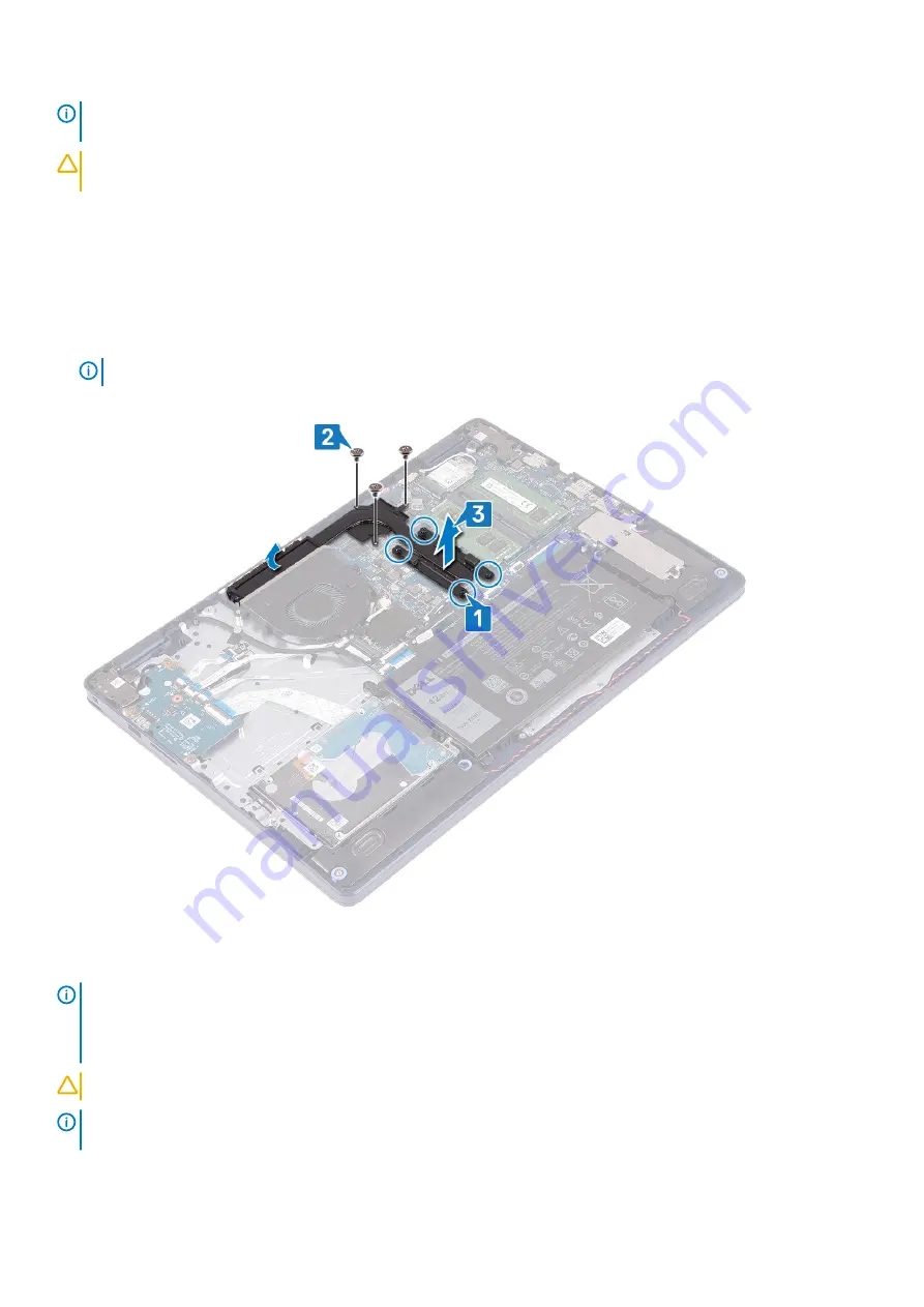
1. In reverse sequential order (4->3->2->1), loosen the four captive screws that secure the heat sink to the system board.
2. Remove the three (M2x3) screws that secure the heat sink to the system board.

NOTE: 

Applicable only to computers shipped with discrete graphics card.

3. Lift the heat sink off the system board.

Replacing the heat sink

NOTE: 

Before working inside your computer, read the safety information that shipped with your computer and follow 

the steps in 

Before working inside your computer

. After working inside your computer, follow the instructions in 

After 

working inside your computer

. For more safety best practices, see the Regulatory Compliance home page at 

www.dell.com/regulatory_compliance

.

CAUTION: 

Incorrect alignment of the heat sink can damage the system board and processor.

NOTE: 

If either the system board or the heat sink is replaced, use the thermal pad/paste provided in the kit to ensure 

that thermal conductivity is achieved.

Removing and installing components

37

Содержание Inspiron 5593

Страница 1: ...Inspiron 5593 Service Manual Regulatory Model P90F Regulatory Type P90F002 ...

Страница 2: ...amage to hardware or loss of data and tells you how to avoid the problem WARNING A WARNING indicates a potential for property damage personal injury or death 2019 Dell Inc or its subsidiaries All rights reserved Dell EMC and other trademarks are trademarks of Dell Inc or its subsidiaries Other trademarks may be trademarks of their respective owners 2019 08 Rev A00 ...

Страница 3: ...odules 19 Removing the memory modules 19 Replacing the memory modules 20 Wireless card 20 Removing the wireless card 20 Replacing the wireless card 21 Fan 22 Removing the fan 22 Replacing the fan 23 Solid state drive Intel Optane 24 Removing the solid state drive Intel Optane 24 Replacing the solid state drive Intel Optane 26 Hard drive 28 Removing the hard drive 28 Replacing the hard drive 30 Tou...

Страница 4: ...m rest and keyboard assembly 58 Replacing the palm rest and keyboard assembly 59 Display bezel 60 Removing the display bezel 60 Replacing the display bezel 61 Camera 62 Removing the camera 62 Replacing the camera 63 Display panel 64 Removing the display panel 64 Replacing the display panel 66 Display cable 68 Removing the display cable 68 Replacing the display cable 69 Display back cover and anten...

Страница 5: ...ing 79 Enhanced Pre Boot System Assessment ePSA diagnostics 79 Running the ePSA diagnostics 79 System diagnostic lights 79 Recovering the operating system 80 Flashing the BIOS 80 Enabling Intel Optane memory 81 Disabling Intel Optane memory 81 Flashing BIOS USB key 81 WiFi power cycle 81 Flea power release 82 6 Getting help and contacting Dell 83 Contents 5 ...

Страница 6: ...nside your computer ground yourself by using a wrist grounding strap or by periodically touching an unpainted metal surface such as the metal at the back of the computer While you work periodically touch an unpainted metal surface to dissipate static electricity which could harm internal components CAUTION When you disconnect a cable pull on its connector or on its pull tab not on the cable itself...

Страница 7: ...ield Service kit includes three main components anti static mat wrist strap and bonding wire Components of an ESD field service kit The components of an ESD field service kit are Anti Static Mat The anti static mat is dissipative and parts can be placed on it during service procedures When using an anti static mat your wrist strap should be snug and the bonding wire should be connected to the mat ...

Страница 8: ...orming service and that they use anti static bags for transporting sensitive components Transporting sensitive components When transporting ESD sensitive components such as replacement parts or parts to be returned to Dell it is critical to place these parts in anti static bags for safe transport Lifting equipment Adhere to the following guidelines when lifting heavy weight equipment CAUTION Do no...

Страница 9: ... screws are not left attached to such surface when replacing a component NOTE Screw color may vary with the configuration ordered Table 1 Screw list Component Secured to Screw type Quantity Screw image Base cover Palm rest and keyboard assembly M2 5x6 7 Battery Palm rest and keyboard assembly M2x3 3 Display panel Display back cover and antenna assembly M2 5x2 5 6 Display panel Display back cover a...

Страница 10: ...6x2 3 Touchpad Palm rest and keyboard assembly M1 6x2 2 Wireless card bracket System board M2x3 1 Base cover Removing the base cover NOTE Before working inside your computer read the safety information that shipped with your computer and follow the steps in Before working inside your computer After working inside your computer follow the instructions in After working inside your computer For more ...

Страница 11: ...ver starting from the indents at the display hinges located at the top left and top right corners of the computer base 4 Lift the base cover off the palm rest and keyboard assembly Removing and installing components 11 ...

Страница 12: ...cable only if you want to further remove any other component from your computer 5 Peel the tape that adheres the battery cable to the connector and disconnect the battery cable from the system board 12 Removing and installing components ...

Страница 13: ...eps in Before working inside your computer After working inside your computer follow the instructions in After working inside your computer For more safety best practices see the Regulatory Compliance home page at www dell com regulatory_compliance Procedure 1 Connect the battery cable to the system board 2 Adhere the tape that secures the battery cable to the connector on the system board if appl...

Страница 14: ... the base cover into place starting from the power adapter port CAUTION To avoid accidental damage to the power adapter port do not press the base cover against the power adapter port when you snap the base cover to the computer base 14 Removing and installing components ...

Страница 15: ...en screws M2 5x6 that secure the base cover to the palm rest and keyboard assembly 5 Tighten the two captive screws that secure the base cover to the palm rest and keyboard assembly Removing and installing components 15 ...

Страница 16: ...batteries Discharge the battery as much as possible before removing it from the system This can be done by disconnecting the AC adapter from the system to allow the battery to drain Do not crush drop mutilate or penetrate the battery with foreign objects Do not expose the battery to high temperatures or disassemble battery packs and cells Do not apply pressure to the surface of the battery Do not ...

Страница 17: ...tes Remove the base cover Procedure 1 Peel off the tape that secures the battery cable to the battery connector 2 Disconnect the battery cable from the system board 3 Remove the three screws M2x3 that secure the battery to the palm rest and keyboard assembly 4 Slide and lift the battery off the palm rest and keyboard assembly Replacing the battery NOTE Before working inside your computer read the ...

Страница 18: ... to free it as puncturing bending or crushing a Lithium ion battery can be dangerous In such an instance contact for assistance and further instructions If the battery gets stuck inside your computer as a result of swelling do not try to release it as puncturing bending or crushing a lithium ion battery can be dangerous In such an instance contact Dell technical support for assistance See www dell...

Страница 19: ...w the instructions in After working inside your computer For more safety best practices see the Regulatory Compliance home page at www dell com regulatory_compliance Prerequisites Remove the base cover Procedure 1 Locate the memory module on your computer 2 Use your fingertips to carefully spread apart the securing clips on each end of the memory module slot until the memory module pops up 3 Remov...

Страница 20: ... slot at an angle 3 Press the memory module down until it clicks into place NOTE If you do not hear the click remove the memory module and reinstall it Post requisites Replace the base cover Wireless card Removing the wireless card NOTE Before working inside your computer read the safety information that shipped with your computer and follow the steps in Before working inside your computer After w...

Страница 21: ...tenna cables from the wireless card 5 Slide and remove the wireless card from the wireless card slot Replacing the wireless card NOTE Before working inside your computer read the safety information that shipped with your computer and follow the steps in Before working inside your computer After working inside your computer follow the instructions in After Removing and installing components 21 ...

Страница 22: ...ard bracket on the wireless card 3 Align the notch on the wireless card with the tab on the wireless card slot and insert the wireless card at an angle into the wireless card slot 4 Replace the screw M2x3 that secures the wireless card bracket to the system board Post requisites Replace the base cover Fan Removing the fan NOTE Before working inside your computer read the safety information that sh...

Страница 23: ...eps in Before working inside your computer After working inside your computer follow the instructions in After working inside your computer For more safety best practices see the Regulatory Compliance home page at www dell com regulatory_compliance Procedure 1 Using the alignment post align the screw holes on the fan with the screw holes on the palm rest and keyboard assembly 2 Replace the two scr...

Страница 24: ...ctions in After working inside your computer For more safety best practices see the Regulatory Compliance home page at www dell com regulatory_compliance Prerequisites Remove the base cover Procedure to remove the M 2 2230 solid state drive 1 Loosen the captive screw that secures the M 2 2230 shield to the palm rest and keyboard assembly 2 Remove the screw M2x3 that secures the M 2 2230 shield to ...

Страница 25: ... captive screw that secures the M 2 2280 thermal shield to the palm rest and keyboard assembly 2 Remove the screw M2x3 that secures the M 2 2280 thermal shield and the solid state drive to the palm rest and keyboard assembly 3 Slide and remove the M 2 2280 thermal shield from the slot on the palm rest and keyboard assembly 4 Lift the solid state drive at an angle and remove it from the M 2 slot on...

Страница 26: ...er working inside your computer follow the instructions in After working inside your computer For more safety best practices see the Regulatory Compliance home page at www dell com regulatory_compliance CAUTION Solid state drives are fragile Exercise care when handling the solid state drive Procedure to replace M 2 2230 solid state drive 1 Place the solid state drive into the slot at the back of t...

Страница 27: ... secures the M 2 2230 thermal shield to the palm rest and keyboard assembly Procedure to replace the M 2 2280 solid state drive 1 Align the notch on the solid state drive with the tab on the M 2 slot and slide the solid state drive into place 2 Insert the tab of the M 2 2280 thermal shield into the slot on the palm rest and keyboard assembly 3 Replace the screw M2x3 that secures the M 2 2280 therm...

Страница 28: ...tructions in After working inside your computer For more safety best practices see the Regulatory Compliance home page at www dell com regulatory_compliance CAUTION Hard drives are fragile Exercise care when handling the hard drive CAUTION To avoid data loss do not remove the hard drive while the computer is in sleep or on state Prerequisites 1 Remove the base cover 2 Remove the battery Procedure ...

Страница 29: ... the interposer from the hard drive assembly 5 Remove the four screws M3x3 that secure the hard drive bracket to the hard drive 6 Lift the hard drive off the hard drive bracket Removing and installing components 29 ...

Страница 30: ...ide your computer follow the instructions in After working inside your computer For more safety best practices see the Regulatory Compliance home page at www dell com regulatory_compliance CAUTION Hard drives are fragile Exercise care when handling the hard drive Procedure 1 Align the screw holes on the hard drive bracket with the screw holes on the hard drive 2 Replace the four screws M3x3 that s...

Страница 31: ...5 Replace the three screws M2x3 that secure the hard drive assembly to the palm rest and keyboard assembly 6 Connect the hard drive cable to the system board and close the latch to secure the cable Post requisites 1 Replace the battery 2 Replace the base cover Removing and installing components 31 ...

Страница 32: ...ge at www dell com regulatory_compliance Prerequisites 1 Remove the base cover 2 Remove the battery Procedure 1 Open the latch and disconnect the touchpad cable from the system board 2 Remove the three screws M1 6x2 that secure the touchpad bracket to the palm rest and keyboard assembly 3 Lift the touchpad bracket off the palm rest and keyboard assembly 4 Remove the two screws M1 6x2 that secure t...

Страница 33: ...t practices see the Regulatory Compliance home page at www dell com regulatory_compliance Procedure NOTE Ensure that the touchpad is aligned with the guides available on the palm rest and keyboard assembly and the gap on either sides of the touchpad is equal 1 Using the alignment post slide and place the touchpad into the slot on the palm rest and keyboard assembly 2 Replace the two screws M1 6x2 ...

Страница 34: ...oard assembly 4 Replace the three screws M1 6x2 that secure the touchpad to the palm rest and keyboard assembly 5 Slide the touchpad cable into the connector on the system board and close the latch to secure the cable 34 Removing and installing components ...

Страница 35: ...in After working inside your computer For more safety best practices see the Regulatory Compliance home page at www dell com regulatory_compliance Prerequisites 1 Remove the base cover 2 Remove the solid state drive Intel Optane Procedure 1 Disconnect the speaker cable from the system board 2 Note the speaker cable routing and remove it from the routing guides on palm rest and keyboard assembly 3 ...

Страница 36: ...speaker cable to the system board 2 Using the alignment posts and the rubber grommets place the speakers in the slots on the palm rest and keyboard assembly and route the speaker cables along the routing guides Post requisites 1 Replace the solid state drive Intel Optane 2 Replace the base cover Heat sink Removing the heat sink NOTE Before working inside your computer read the safety information t...

Страница 37: ...nly to computers shipped with discrete graphics card 3 Lift the heat sink off the system board Replacing the heat sink NOTE Before working inside your computer read the safety information that shipped with your computer and follow the steps in Before working inside your computer After working inside your computer follow the instructions in After working inside your computer For more safety best pr...

Страница 38: ...sites Replace the base cover Display assembly Removing the display assembly NOTE Before working inside your computer read the safety information that shipped with your computer and follow the steps in Before working inside your computer After working inside your computer follow the instructions in After working inside your computer For more safety best practices see the Regulatory Compliance home ...

Страница 39: ...lace it on the edge of the table in a position that allows access to the screws on the display hinges 5 Remove the six screws M2 5x5 that secure the left and the right hinges to the system board and the palm rest and keyboard assembly NOTE Hold the display assembly so that it does not fall off when the last screw is removed 6 Lift the display assembly off the palm rest and keyboard assembly Removi...

Страница 40: ...7 After performing all the above steps you are left with display assembly 40 Removing and installing components ...

Страница 41: ...ompliance home page at www dell com regulatory_compliance Procedure NOTE Ensure that the hinges are opened to 90 degrees before replacing the display assembly on the palm rest and keyboard assembly 1 With the palm rest and keyboard assembly at the edge of the table align the screw holes on the palm rest and keyboard assembly with the screw holes on the display hinges 2 Replace the six screws M2 5x...

Страница 42: ...les on the palm rest and keyboard assembly 5 Route the display cable through the routing guides on the fan and the palm rest and keyboard assembly 6 Slide the display cable to the connector on the system board and close the latch to secure the display cable 42 Removing and installing components ...

Страница 43: ...ns in After working inside your computer For more safety best practices see the Regulatory Compliance home page at www dell com regulatory_compliance Prerequisites 1 Remove the base cover 2 Remove the wireless card Procedure 1 Disconnect the power adapter port cable from the system board 2 Note the power adapter port cable routing and remove it from the routing guides on the palm rest and keyboard...

Страница 44: ...fter working inside your computer For more safety best practices see the Regulatory Compliance home page at www dell com regulatory_compliance Procedure 1 Using the alignment post place the power adapter port in the slot on the palm rest and keyboard assembly 2 Route the power adapter port cable through the routing guides on the palm rest and keyboard assembly 3 Connect the power adapter port cabl...

Страница 45: ...rogram s settings 1 Remove the base cover 2 Remove the battery 3 Remove the hard drive with Intel optane Procedure 1 Open the latch and disconnect the fingerprint reader board cable from the I O board NOTE This step is applicable only for computers shipped with the optional fingerprint reader 2 Open the latch and disconnect the power button board cable from the I O board 3 Open the latch and disco...

Страница 46: ...ace the three screws M2x4 that secure the I O board to the palm rest and keyboard assembly 3 Connect the I O board cable to the I O board and close the latch to secure the cable 4 Connect the fingerprint reader cable to the I O board and close the latch to secure the cable NOTE This step is applicable only for computers shipped with the optional fingerprint reader 5 Connect the power button board ...

Страница 47: ...fety best practices see the Regulatory Compliance home page at www dell com regulatory_compliance CAUTION Removing the coin cell battery resets the BIOS setup program s settings to default It is recommended that you note the BIOS setup program s settings before removing the coin cell battery Prerequisites CAUTION Removing the coin cell battery resets the BIOS setup program s settings to default Be...

Страница 48: ...battery NOTE Before working inside your computer read the safety information that shipped with your computer and follow the steps in Before working inside your computer After working inside your computer follow the instructions in After working inside your computer For more safety best practices see the Regulatory Compliance home page at www dell com regulatory_compliance Procedure The coin cell b...

Страница 49: ...ide your computer follow the instructions in After working inside your computer For more safety best practices see the Regulatory Compliance home page at www dell com regulatory_compliance Prerequisites 1 Remove the base cover 2 Remove the battery 3 Remove the I O board Procedure 1 Remove the two screws M2x3 that secure the power button to the palm rest and keyboard assembly 2 Lift the power butto...

Страница 50: ...the power button board to the palm rest and keyboard assembly Post requisites 1 Replace the I O board 2 Replace the battery 3 Replace the base cover System board Removing the system board NOTE Before working inside your computer read the safety information that shipped with your computer and follow the steps in Before working inside your computer After working inside your computer follow the instr...

Страница 51: ...dure 1 Disconnect the power adapter port cable from the system board 2 Disconnect the speaker cable from the system board 3 Open the latch and disconnect the keyboard cable from the system board 4 Open the latch and disconnect the keyboard back light cable from the system board 5 Open the latch and disconnect the touchpad cable from the system board 6 Open the latch and disconnect the hard drive c...

Страница 52: ...10 Remove the screw M2x4 that secures the system board to palm rest and keyboard assembly 11 Lift the system board off the palm rest and keyboard assembly 52 Removing and installing components ...

Страница 53: ...iance NOTE Your computer s Service Tag is stored in the system board You must enter the Service Tag in the BIOS setup program after you replace the system board NOTE Replacing the system board removes any changes you have made to the BIOS using the BIOS setup program You must make the appropriate changes again after you replace the system board Procedure 1 Align the screw hole on the system board ...

Страница 54: ...e system board and close the latch 6 Slide the hard drive cable into the connector on the system board and close the latch 7 Slide the touchpad cable into the connector on the system board and close the latch 8 Slide the keyboard back light cable into the connector on the system board and close the latch 9 Slide the keyboard cable into the connector on the system board and close the latch 10 Conne...

Страница 55: ... battery 8 Replace the base cover Entering the Service Tag in the BIOS setup program 1 Turn on or restart your computer 2 Press F2 when the Dell logo is displayed to enter the BIOS setup program 3 Navigate to the Main tab and enter the Service Tag in the Service Tag Input field NOTE Service tag is the alphanumeric identifier located at the back side of your computer Removing and installing compone...

Страница 56: ...ove the base cover 2 Remove the battery 3 Remove the solid state drive Intel Optane 4 Remove the fan 5 Remove the heat sink 6 Remove the wireless card 7 Remove the system board NOTE When removing and replacing the power button with fingerprint reader do not remove the heat sink from the system board Procedure 1 Remove the two screws M2x3 that secure the power button with fingerprint reader to the ...

Страница 57: ...y Compliance home page at www dell com regulatory_compliance NOTE Applicable only for computers that are shipped with fingerprint reader Procedure 1 Using the alignment posts align and place the fingerprint reader board on the palm rest and keyboard assembly 2 Adhere the fingerprint reader cable on the palm rest and keyboard assembly 3 Place the power button on the palm rest and keyboard assembly ...

Страница 58: ...on that shipped with your computer and follow the steps in Before working inside your computer After working inside your computer follow the instructions in After working inside your computer For more safety best practices see the Regulatory Compliance home page at www dell com regulatory_compliance Prerequisites 1 Remove the base cover 2 Remove the battery 3 Remove the fan 4 Remove the solid stat...

Страница 59: ...left with the palm rest and keyboard assembly Replacing the palm rest and keyboard assembly NOTE Before working inside your computer read the safety information that shipped with your computer and follow the steps in Before working inside your computer After working inside your computer follow the instructions in After working inside your computer For more safety best practices see the Regulatory ...

Страница 60: ...e 11 Replace the fan 12 Replace the battery 13 Replace the base cover Display bezel Removing the display bezel NOTE Before working inside your computer read the safety information that shipped with your computer and follow the steps in Before working inside your computer After working inside your computer follow the instructions in After working inside your computer For more safety best practices ...

Страница 61: ...mputer read the safety information that shipped with your computer and follow the steps in Before working inside your computer After working inside your computer follow the instructions in After working inside your computer For more safety best practices see the Regulatory Compliance home page at www dell com regulatory_compliance Procedure Align the display bezel with the display back cover and a...

Страница 62: ...ide your computer follow the instructions in After working inside your computer For more safety best practices see the Regulatory Compliance home page at www dell com regulatory_compliance Prerequisites 1 Remove the base cover 2 Remove the wireless card 3 Remove the display assembly 4 Remove the display bezel Procedure 1 Using a plastic scribe gently pry the camera off the display back cover and a...

Страница 63: ...working inside your computer After working inside your computer follow the instructions in After working inside your computer For more safety best practices see the Regulatory Compliance home page at www dell com regulatory_compliance Procedure 1 Connect the camera cable to the camera module 2 Using the alignment post adhere the camera module to the display back cover and antenna assembly Removing...

Страница 64: ...g inside your computer After working inside your computer follow the instructions in After working inside your computer For more safety best practices see the Regulatory Compliance home page at www dell com regulatory_compliance Prerequisites 1 Remove the base cover 2 Remove the wireless card 3 Remove the display assembly 4 Remove the display bezel Procedure 1 Remove the six screws M2 5x2 5 that s...

Страница 65: ...e display hinges and brackets are shipped together with the display panel as an assembly and do not need to be separated from the display panel 4 Peel the tape adhering the display cable to the back of the display panel 5 Lift the latch and disconnect the display cable from the display panel cable connector 6 Lift the display panel away from the display back cover and antenna assembly Removing and...

Страница 66: ... in After working inside your computer For more safety best practices see the Regulatory Compliance home page at www dell com regulatory_compliance Procedure 1 Place the display panel on a flat and clean surface 2 Connect the display cable to the connector at the back of the display panel and close the latch to secure the cable 3 Adhere the tape that secures the display cable to the back of the di...

Страница 67: ... assembly 5 Replace the two screws M2x3 that secure the display panel to the display back cover and antenna assembly 6 Replace the six screws M2 5x2 5 that secure the display panel to the display back cover and antenna assembly Removing and installing components 67 ...

Страница 68: ...n Before working inside your computer After working inside your computer follow the instructions in After working inside your computer For more safety best practices see the Regulatory Compliance home page at www dell com regulatory_compliance Prerequisites 1 Remove the base cover 2 Remove the wireless card 3 Remove the display assembly 4 Remove the display bezel 5 Remove the display panel Procedu...

Страница 69: ... computer After working inside your computer follow the instructions in After working inside your computer For more safety best practices see the Regulatory Compliance home page at www dell com regulatory_compliance Procedure 1 Route the display cable along the routing guides starting from the bottom of the display near the hinges 2 Route the rest of the display cable along the routing guides on t...

Страница 70: ...hipped with your computer and follow the steps in Before working inside your computer After working inside your computer follow the instructions in After working inside your computer For more safety best practices see the Regulatory Compliance home page at www dell com regulatory_compliance Prerequisites 1 Remove the base cover 2 Remove the wireless card 3 Remove the display assembly 4 Remove the ...

Страница 71: ...tion that shipped with your computer and follow the steps in Before working inside your computer After working inside your computer follow the instructions in After working inside your computer For more safety best practices see the Regulatory Compliance home page at www dell com regulatory_compliance Procedure Place the display back cover and antenna assembly on a clean and flat surface Removing ...

Страница 72: ...place the display cable 2 Replace the display panel 3 Replace the camera 4 Replace the display bezel 5 Replace the display assembly 6 Replace the wireless card 7 Replace the base cover 72 Removing and installing components ...

Страница 73: ...down list 15 Click Download to download the audio driver for your computer 16 After the download is complete navigate to the folder where you saved the audio driver file 17 Double click the audio driver file icon and follow the instructions on the screen to install the driver Downloading the network driver 1 Turn on your computer 2 Go to www dell com support 3 Enter the Service Tag of your compute...

Страница 74: ...y Review the installation summary to identify if manual installation is necessary 13 For manual download and installation click Category 14 Click Chipset in the drop down list 15 Click Download to download the chipset driver for your computer 16 After the download is complete navigate to the folder where you saved the saved the chipset driver file 17 Double click the chipset driver file icon and f...

Страница 75: ...les can be installed automatically Review the installation summary to identify if manual installation is necessary 13 For manual download and installation click Category 14 Click Network in the drop down list 15 Click Download to download the WiFi driver for your computer 16 After the download is complete navigate to the folder where you saved the WiFi driver file 17 Double click the WiFi driver i...

Страница 76: ...ssary your computer starts to download and install SupportAssist NOTE Review on screen instructions for browser specific instructions 8 Click View Drivers for My System 9 Click Download and Install to download and install all driver updates detected for your computer 10 Select a location to save the files 11 If prompted approve requests from User Account Control to make changes on the system 12 Th...

Страница 77: ...ices Entering BIOS setup program 1 Turn on or restart your computer 2 During POST when the DELL logo is displayed watch for the F2 prompt to appear and then press F2 immediately NOTE The F2 prompt indicates that the keyboard is initialized This prompt can appear very quickly so you must watch for it and then press F2 If you press F2 before the F2 prompt this keystroke is lost If you wait too long ...

Страница 78: ...Diagnostics NOTE Choosing Diagnostics will display the ePSA diagnostics screen The boot sequence screen also displays the option to access the System Setup screen Clearing CMOS settings CAUTION Clearing CMOS settings will reset the BIOS settings on your computer 1 Remove the base cover 2 Disconnect the battery cable from the system board 3 Remove the coin cell battery 4 Wait for one minute 5 Repla...

Страница 79: ...ont page is displayed 5 Click the arrow in the lower right corner to go to the page listing The items detected are listed 6 To run a diagnostic test on a specific device press Esc and click Yes to stop the diagnostic test 7 Select the device from the left pane and click Run Tests 8 If there are any issues error codes are displayed Note the error code and validation number and contact Dell System d...

Страница 80: ...lone tool that is preinstalled in all Dell computers installed with Windows 10 operating system It consists of tools to diagnose and troubleshoot issues that may occur before your computer boots to the operating system It enables you to diagnose hardware issues repair your computer back up your files or restore your computer to its factory state You can also download it from the Dell Support websi...

Страница 81: ...e Intel Rapid Storage Technology 2 Click Intel Rapid Storage Technology The Intel Rapid Storage Technology window is displayed 3 On the Intel Optane memory tab click Disable to disable the Intel Optane memory NOTE For computers in which Intel Optane memory acts as a primary storage do not disable the Intel Optane memory The Disable option will be grayed out 4 Click Yes if you accept the warning Th...

Страница 82: ...at remains on the computer even after it has been powered off and the battery has been removed The following procedure provides the instructions on how to conduct flea power release 1 Turn off your computer 2 Disconnect the power adapter from your computer 3 Press and hold the power button for 15 seconds to drain the flea power 4 Connect the power adapter to your computer 5 Turn on your computer 8...

Страница 83: ... the related articles Learn and know the following information about your product Product specifications Operating system Setting up and using your product Data backup Troubleshooting and diagnostics Factory and system restore BIOS information See Me and My Dell at www dell com support manuals To locate the Me and My Dell relevant to your product identify your product through one of the following ...

Отзывы: