
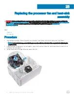

Replacing the processor fan and heat-sink
assembly
WARNING:
Before working inside your computer, read the safety information that shipped with your computer and follow the
steps in
Before working inside your computer
. After working inside your computer, follow the instructions in
. For more safety best practices, see the Regulatory Compliance home page at
Topics:
•
•
Procedure
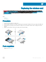
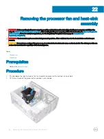
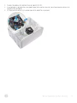
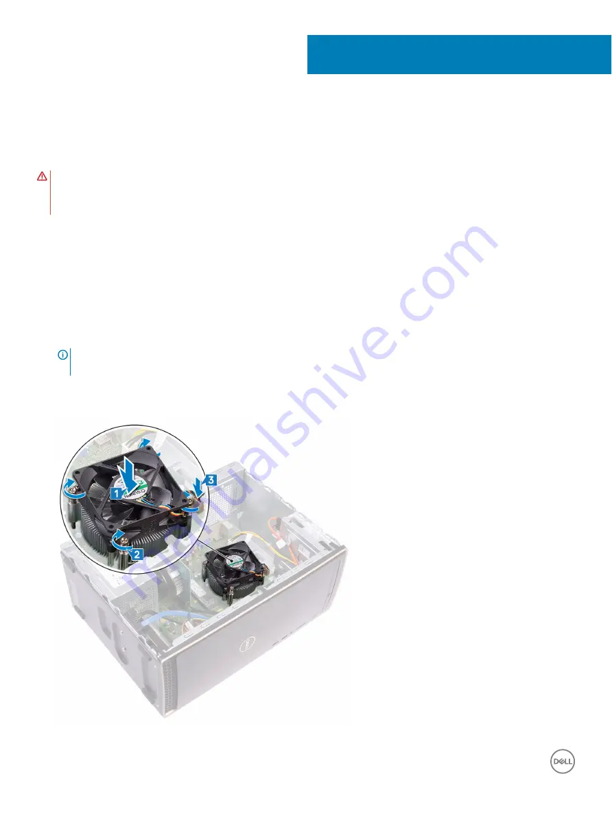
1
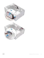
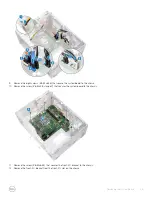
Place and align the captive screws on the processor fan and heat-sink assembly with the screw holes on the system board.
NOTE:
As shown in the image, ensure that the processor-fan cable faces the front of the computer before tightening the
captive screws.
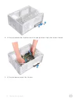
2
In sequential order (as indicated on the system board), tighten the four captive screws that secure the processor fan and heat-sink
assembly to the system board.
3
Connect the processor-fan cable to the system board (FAN CPU).
23
40
Replacing the processor fan and heat-sink assembly
Содержание Inspiron 3670
Страница 15: ...Removing the front bezel 15 ...
Страница 17: ...Post requisites Replace the computer cover Replacing the front bezel 17 ...
Страница 19: ...Removing the memory module 19 ...
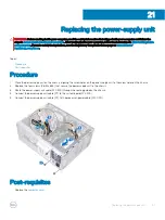
Страница 21: ...Post requisites Replace the computer cover Replacing the memory module 21 ...
Страница 23: ...Removing the solid state drive Intel Optane 23 ...
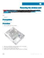
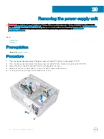
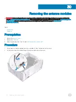
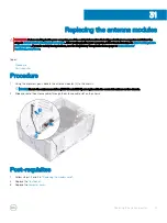
Страница 30: ...30 Removing the wireless card ...
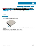
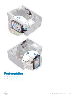
Страница 35: ...Post requisites Replace the computer cover Replacing the optical drive 35 ...
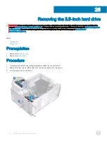
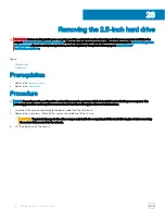
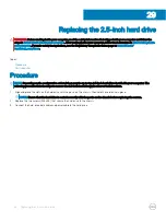
Страница 47: ...Removing the 2 5 inch hard drive 47 ...
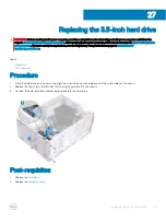
Страница 49: ...Post requisites 1 Replace the front bezel 2 Replace the computer cover Replacing the 2 5 inch hard drive 49 ...
Страница 55: ...Removing the system board 55 ...
Страница 72: ...Post requisites Replace the computer cover 72 System and setup password ...