background image

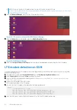
The installation process begins.

Figure 26. Installation of ADVA 18.4 operating system begins

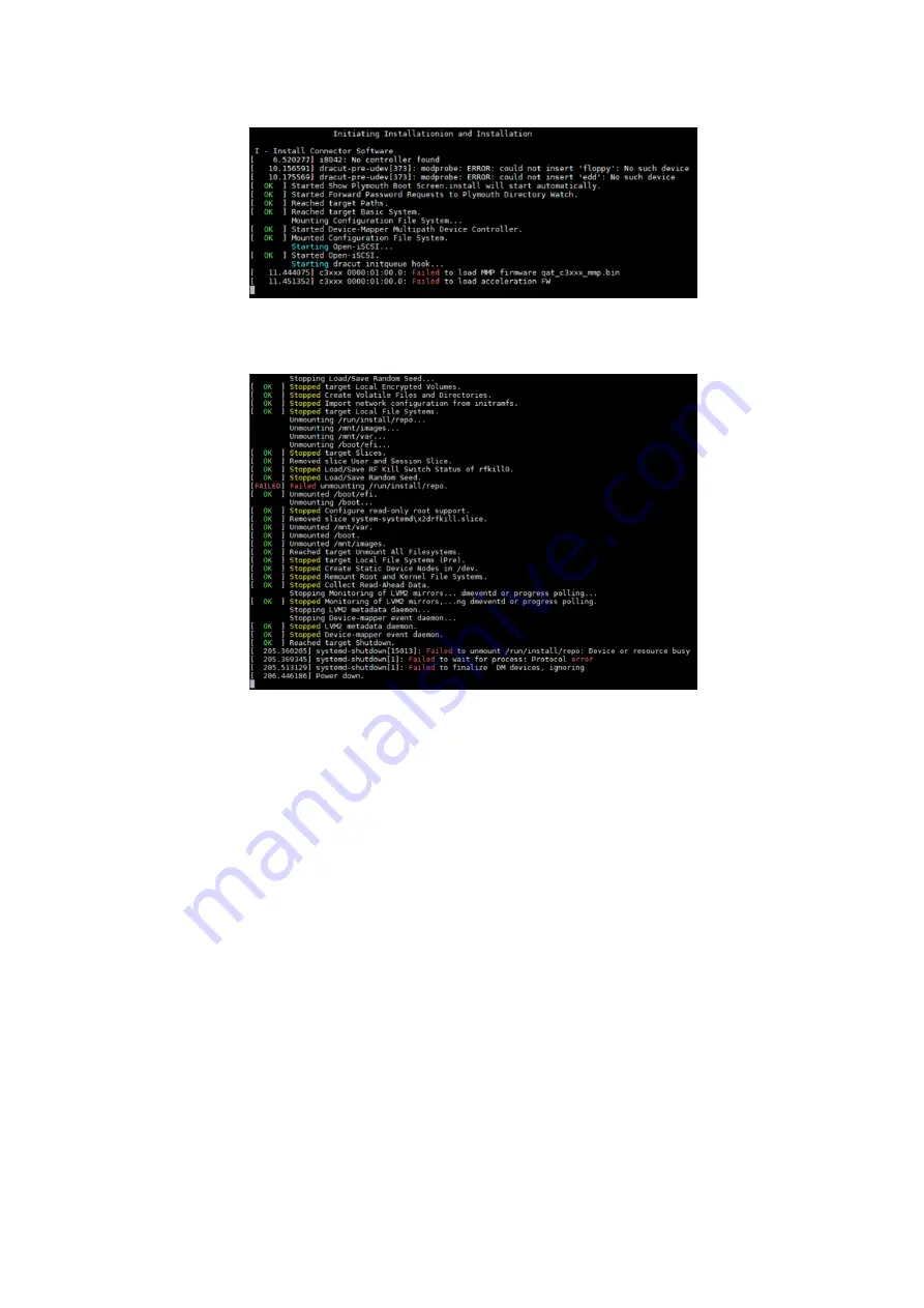
2. Continue to monitor the installation process.

When the installation process is complete, the 

Power down

 message displays in the installation window.

Figure 27. Installation complete screen

After the ADVA operating system is installed, the system powers off.

Configure BIOS to boot from SSD

1. Power up the VEP1405 series system and press 

F2

 to boot into the BIOS.

2. Using the arrow keys, to go to the 

Boot

 tab then press 

Enter

.

3. From the 

Boot Option Priorities

 section, select 

CentOS SATA Flash Drive

 as 

Boot Option #1

, then press 

Enter

.

Configure BIOS and install ADVA 18.4 operating system installation to SSD

23

Содержание EMC VEP1425

Страница 1: ...Virtual Edge Platform 1405 Series Operating System Installation Guide Dell Networking Solutions July 2021 Rev A05 ...

Страница 2: ...ential damage to hardware or loss of data and tells you how to avoid the problem WARNING A WARNING indicates a potential for property damage personal injury or death 2020 Dell Inc or its subsidiaries All rights reserved Dell EMC and other trademarks are trademarks of Dell Inc or its subsidiaries Other trademarks may be trademarks of their respective owners ...

Страница 3: ...ll Red Hat Enterprise Linux 7 5 operating system 18 Start RHEL operating system installation 19 Configure BIOS to boot from SSD 19 Chapter 6 Configure BIOS and install ADVA 18 4 operating system installation to SSD 21 Configure BIOS to boot from USB 21 Install ADVA 18 4 operating system 22 Configure BIOS to boot from SSD 23 Chapter 7 Download and install VMware ESXi 7 0 26 Create bootable USB driv...

Страница 4: ... VEP1405 series before installing the operating system is as follows Table 2 VEP1405 series recommended minimum firmware versions Feature Configuration option 1 Versa ready Configuration option 2 ADVA ready DIAG OS 3 43 3 81 18 3 43 3 81 18 DIAG Tools 3 43 4 81 19 3 43 4 81 19 Firmware Updater 1 6 1 6 BIOS version 4 core 3 48 0 9 11 for VEP1405 series 3 48 0 9 12 for VEP1405N series 4 core option ...

Страница 5: ...USB 3 0 Low energy Bluetooth BLE Two fans VEP1445 8 core 32 GB DDR4 16 GB eMMC 960 GB SSD 2x 2 Wi Fi 6x 1 GB Copper RJ45 2x 10 GB SFP ADVA software installed Trusted Platform Module TPM 2 0 World wide except China 2x USB 3 0 Low energy Bluetooth BLE Two fans VEP1445N 8 core 16 GB DDR4 16 GB eMMC 240 GB SSD 6x 1 GB Copper RJ45 2x 10 GB SFP Versa software installed Trusted Platform Module TPM 2 0 Wo...

Страница 6: ...orm Module TPM 2 0 World wide except China 2x USB 3 0 Two fans NOTE For a listing of the supported optics guidelines for the VEP1405 series see the Virtual Edge Platform 1405 Series Technology Guide Figure 1 VEP1405 series front view 1 Security lock port 2 USB port NOTE An additional USB port is located on the opposite side of the system 3 System status indicator LED Table 4 Front view system stat...

Страница 7: ... accessed in a nonsecure location the system ships from the factory with a plate covering the micro USB port To uncover the port use a 0 2 5 mm Phillips head screwdriver to loosen or remove the screw that holds the plate in place Figure 3 VEP1405 series back view without port cover 1 Micro USB serial console port 2 Reset button NOTE See the Reset button behavior table below for more information 3 ...

Страница 8: ...ush is set by the BIOS in the CMOS RAM Flag allows user to have the operating system detect a long button push Table 7 Chassis physical design Parameter Configuration option 1 Configuration option 2 Height 5 2 cm 2 0 in 5 2 cm 2 0 in Width 20 8 cm 8 1 in 20 8 cm 8 1 in Depth 20 0 cm 7 9 in 20 0 cm 7 9 in Chassis weight with factory installed components 4 core 1 44 kg 3 17 lb 8 core 1 42 kg 3 13 lb...

Страница 9: ...ft Table 9 AC power requirements Parameter Configuration option 1 Configuration option 2 Power supply 100 240 VAC 50 60 Hz 100 240 VAC 50 60 Hz Maximum current draw per system AC 100 VAC 2 0A 240 VAC 1 0A 100 VAC 2 0A 240 VAC 1 0A Power consumption Typical 40 W 16 core 35 W 8 core 20 W 4 core Maximum 50 W 16 core 45 W 8 core 30 W 4 core Typical 40 W 16 core 35 W 8 core Maximum 50 W 16 core 45 W 8 ...

Страница 10: ... communications port using the Microsoft Windows operating system Device Manager Figure 4 Microsoft Windows Device Manager 3 Using a terminal emulator such as PuTTY locate and configure the serial port that the USB connection represents 4 In the Serial field enter the wanted connection name 5 Enter 115200 as the baud rate in the Speed field 6 Select Serial for the Connection type NOTE To save the ...

Страница 11: ...ete key until the Press DEL string displays in the console window Figure 7 Setup screen NOTE If you do not press the Delete key fast enough the boot up screen displays If this occurs you must power the VEP1405 unit off and power it on again to restart the boot up process Create a serial console connection 11 ...

Страница 12: ...Hat Enterprise Linux RHEL ESXi or ADVA operating system 1 Insert the USB drive into the system running Microsoft Windows The Rufus window displays 2 Within the Drive Properties section click the Select button next to the Boot selection section The Browse window displays 3 Go to the location where the ubuntu 18 10 live server amd64 iso file is located then click Open 4 Locate the Partition scheme d...

Страница 13: ...k Open 11 From the linux image line add console ttyS0 115200 as shown in the following figure Figure 11 Edit grub cfg file 12 Save the changes that are made to the grub file then close the file 13 Plug the bootable USB drive that you created in step 1 into any of the USB ports on the sides of the VEP1405 series system NOTE Perform the same steps listed in this section to create a bootable USB driv...

Страница 14: ...row keys to select the Advanced tab Figure 12 Advanced tab 3 Use the arrow keys to select the CSM Configuration listing then press Enter 4 From the Compatibility Support Module Configuration screen change the Boot option filter to UEFI only mode and press Enter Figure 13 Boot option filter 5 From the BIOS screen use the arrow keys to select the Boot tab and press Enter to change the boot option pr...

Страница 15: ...owing steps 1 From the GNU GRUB screen use the arrow keys to select the Install Ubuntu Server option 2 Press the e key to verify the installation menu entry Figure 15 Edit boot entry screen NOTE If the grub cfg file was updated as instructed in the Create bootable USB drive section the linux image line contains the following content console ttyS0 115200 3 Press Ctrl x to start the installation 4 F...

Страница 16: ...te and select the Use An Entire Disk And Set Up LVM option 12 When prompted to select the disk to install to select SATA Flash Drive and then select Done 13 From the Confirm destructive action screen select Continue to proceed with the disk partition 14 In the fields provided enter the required Name Server name and User name then select Done 15 Review the snaps information that is provided and sel...

Страница 17: ...F4 to save and exit the Boot screen 4 When prompted to confirm the option to Save configuration and exit select Yes and press Enter The system starts to boot When the boot process is complete the log in prompt displays Configure BIOS and install Ubuntu 18 04 operating system to SSD 17 ...

Страница 18: ...nter 10 Use the left and right arrow keys to select Yes after the Save configuration and exit prompt displays then press Enter Follow the steps in the next section to boot to the Red Hat 7 5 GRUB installation menu Install Red Hat Enterprise Linux 7 5 operating system To install the Red Hat Enterprise Linux 7 5 operating system perform the following steps 1 Boot into the Red Hat 7 5 GRUB installati...

Страница 19: ...t Installation Source then enter c to continue Start RHEL operating system installation 1 From the installation source screen enter b to start the installation process The installation process begins 2 After the installation is complete remove the usb drive from the device and press Enter to reboot the system Configure BIOS to boot from SSD 1 From the BIOS screen select the Boot tab 2 Boot into th...

Страница 20: ...The system automatically starts to boot 4 From the system boot screen enter your log in credentials in the field provided 20 Configure BIOS and install Red Hat Enterprise Linux operating system to SSD ...

Страница 21: ...USB drive that you created using the instructions from the Create bootable USB drive section and restart the system 2 Boot the VEP1405 series system and press F2 during the boot process to enter the BIOS The BIOS Setup screen displays 3 Select the Advanced menu tab and select CSM Configuration in BIOS Settings Figure 22 CMS configuration screen 4 Within the Boot option filter section select UEFI a...

Страница 22: ...and to exit the selection screen 7 When prompted to confirm the option to Save Exit select Yes and press Enter The system begins to boot Install ADVA 18 4 operating system 1 From the ADVA Connector Customization and Installation screen press I then Enter Figure 25 ADVA Connector Customization and Installation screen 22 Configure BIOS and install ADVA 18 4 operating system installation to SSD ...

Страница 23: ...27 Installation complete screen After the ADVA operating system is installed the system powers off Configure BIOS to boot from SSD 1 Power up the VEP1405 series system and press F2 to boot into the BIOS 2 Using the arrow keys to go to the Boot tab then press Enter 3 From the Boot Option Priorities section select CentOS SATA Flash Drive as Boot Option 1 then press Enter Configure BIOS and install A...

Страница 24: ... Save Changes and Exit listing then press the Enter key The Save Exit Setup window displays 6 Highlight Yes then press the Enter key Figure 29 Save configuration confirmation screen The system starts to boot The ADVA login screen displays 24 Configure BIOS and install ADVA 18 4 operating system installation to SSD ...

Страница 25: ...Figure 30 ADVA login screen Configure BIOS and install ADVA 18 4 operating system installation to SSD 25 ...

Страница 26: ...ing to Dell EMC vSphere and vSAN 7 0 Guide 2 Save the ISO file to a recognizable and accessible location on your system 3 After saving the ISO file insert the USB drive The Rufus window displays 4 Within the Drive Properties section click the Select button next to the Boot selection section The Browse window displays 5 Go to the location where the VMware VMvisor Installer 7 0 0 16324942 x86_64 Del...

Страница 27: ...Using the arrow keys select CSM Configuration and then press Enter Figure 32 BIOS screen Advanced tab 4 From the CSM Configuration screen verify that UEFI is selected for the Boot option filter Figure 33 CSM Configuration screen 5 From the Boot Configuration screen configure the USB stick as Boot Option 1 and then press Enter to save the change Download and install VMware ESXi 7 0 27 ...

Страница 28: ...l the VMware ESXi 7 0 operating system perform the following steps 1 From the Welcome to the VMware ESXi 7 0 Installation screen press Enter to continue The End User License Agreement EULA screen displays 2 Use the arrow keys to review the information provided within the EULA and if you agree to the terms press F11 to Accept and Continue The Select a Disk to Install or Upgrade screen displays 3 Wh...

Страница 29: ...F11 to proceed with the installation The ESXi installation status screen displays followed by the Installation Complete screen 7 Remove the USB drive from the system and press Enter The VEP1405 system reboots Configure BIOS to boot from SSD To configure the BIOS to boot from the SSD 1 After the system reboots press the Delete key to enter the BIOS The BIOS screen displays 2 Use the arrow keys to s...

Страница 30: ...screen 7 From the VMware ESXi 7 0 screen press F2 to configure the network The Authentication Required screen displays 8 In the field provided enter the required password then press Enter NOTE The Login Name field is already populated This autopopulation only occurs at the log in screen The System Customization screen displays 9 From the System Customization screen select Configure Management Netw...

Страница 31: ...creen select IPv4 Configuration and press Enter 13 Within the IPv4 Configuration screen and if you are using static addressing select the Set Static IPv4 address and network configuration option 14 Using the arrow keys go to the IPv4 Address Subnet Mask and Default Gateway fields and enter the required information 15 After entering the required information in each field press Enter to save the cha...

Страница 32: ...Figure 43 Confirm management network settings screen 32 Download and install VMware ESXi 7 0 ...

Страница 33: ...ierra Wireless modem admin versa flexvnf mmcli L Found 1 modems org freedesktop ModemManager1 Modem 0 Sierra Wireless Incorporated MC7455 4 Verify the WAN interface status of the modem by running the following Versa CLI command admin versa flexvnf cli admin versa flexvnf cli show interfaces wwan status brief interfaces wwan status brief vni 0 100 interface status Configured hw status Modem Detecte...

Страница 34: ...P 1405 or 4600 series of systems running ESXi perform the following steps 1 To enable the LTE card select Enable ESXi Shell from the Troubleshooting Mode Options menu 2 Select Enable SSH and then press Enter to enable the service 3 Log in to the ESXi shell and add the following entries in the passthru map file at etc vmware passthru map 168c 003c d3d0 false 4 Connect the LTE modem to the VEP syste...

Страница 35: ...go to https www inseego com software downloads 10 Connect the modem to the network by performing the following steps a From the taskbar click the Windows icon b Within the application screen click the Settings icon The Windows Settings screen displays c From the Windows Settings screen click the Network Internet icon The Network Internet screen displays d Click the Cellular listing verify that the...

Страница 36: ...Figure 49 Command Prompt screen 36 LTE modem detection ...

Отзывы: