background image

LED behavior

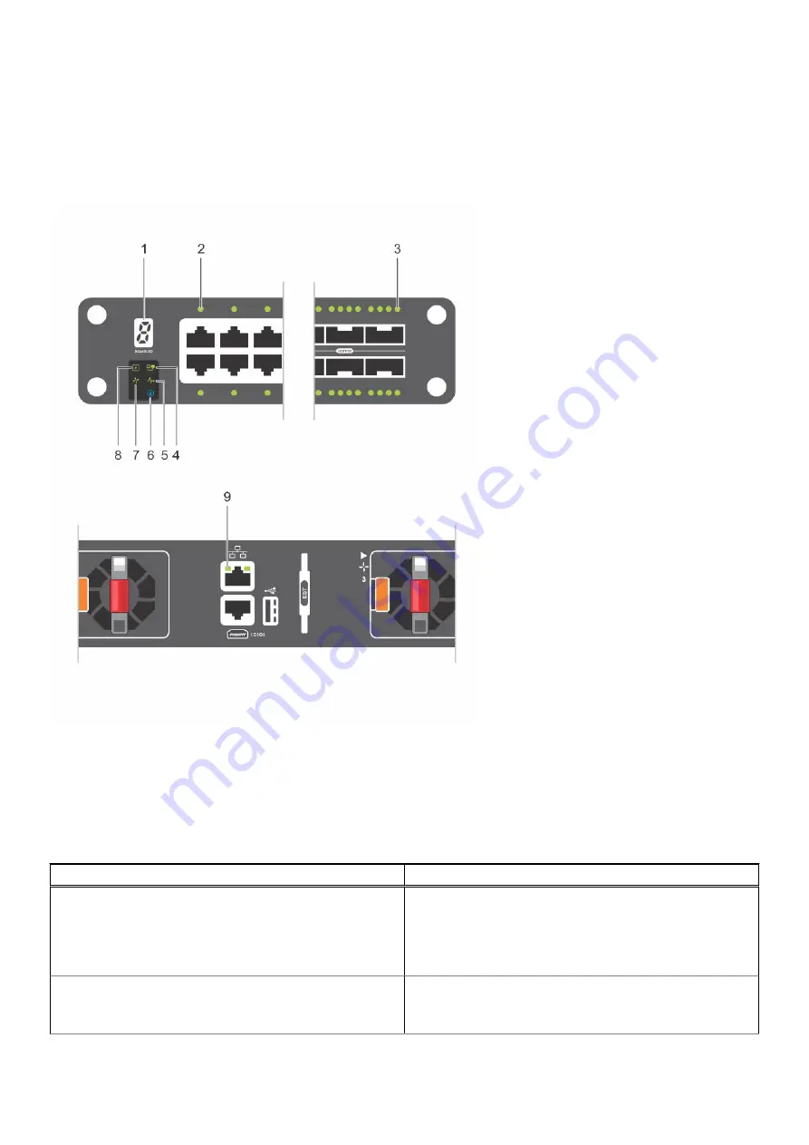
The following S5148F-ON switch LED behavior is seen during open networking installation environment (ONIE) operations:

S5148F-ON LEDs

1. Stack ID LED

2. Port Activity LED

3. Port Activity LED

4. Master LED

5. System LED

6. Locator LED

7. Fan LED

8. Power LED

9. RJ-45 Ethernet Port LED: Left is activity; right is link.

Table 1. S5148F-ON switch LED behavior 

LED

Description

System Status/Health LED

Solid green—Normal operation

Blinking green—Booting

Solid yellow—Critical system error

Blinking yellow—Noncritical system error, fan failure, or
power supply failure

Power LED

Off—No power

Solid Green—Normal operation

Solid yellow—POST is in process

S5148F-ON switch

9

Содержание EMC PowerSwitch S5148F-ON

Страница 1: ...Dell EMC PowerSwitch S5148F ON Installation Guide July 2021 July 2021 Rev A04 ...

Страница 2: ...tial damage to hardware or loss of data and tells you how to avoid the problem WARNING A WARNING indicates a potential for property damage personal injury or death 2017 2021 Dell Inc or its subsidiaries All rights reserved Dell EMC and other trademarks are trademarks of Dell Inc or its subsidiaries Other trademarks may be trademarks of their respective owners ...

Страница 3: ...pter 4 NEBS compliance 15 Important information 15 NEBS compliant ground installation 15 Chapter 5 S5148F ON switch installation 18 Rack or cabinet hardware installation 18 ReadyRails installation 19 Tool less square hole installation 19 Two post flush mount installation 20 Two post center mount installation 21 Four post threaded installation 22 Switch installation 23 1U front rack installation 23...

Страница 4: ... 36 USB storage mount 36 Before you install an OS 37 ONIE service discovery 38 Chapter 9 Specifications 39 Chassis physical design 39 IEEE standards 40 Agency compliance 41 USA Federal Communications Commission statement 41 European Union EMC directive conformance statement 41 Japan VCCI compliance for class A equipment 42 Korean certification of compliance 42 Safety standards and compliance agenc...

Страница 5: ... limits of Class 1 laser radiation Figure 1 Class 1 laser product tag NOTE When no cable is connected visible and invisible laser radiation may emit from the aperture of the optical transceiver ports Avoid exposure to laser radiation Do not stare into open apertures Regulatory Marketing model S5148F ON is represented by the regulatory model E21W and the regulatory type E21W001 Topics Related docum...

Страница 6: ...n CAUTION The Caution icon signals information about situations that could result in equipment damage or loss of data NOTE The Warning icon signals information about hardware handling that could result in injury NOTE The ESD Warning icon requires that you take electrostatic precautions when handling the device 6 About this guide ...

Страница 7: ... aggregation and core switches The switch includes two hot swappable AC or DC power supply units PSUs and four hot swappable fan units The S5148F ON switch includes 54 SFP28 and QSFP28 ports for Ethernet only configurations The SFP28 ports support forty eight 1 10 25GbE The QSFP28 ports support six 40 100GbE Figure 2 S5148F ON switch I O side view 1 Stack ID 2 Forty eight SFP28GbE ports 3 Six QSFP...

Страница 8: ...Rangeley central processing unit CPU system with 8GB DDR III RAM 16GB iSLC mSATA SSD One 10 100 1000BaseT Ethernet management port Two hot swappable redundant power supplies Four hot swappable fan modules Standard 1U switch Physical dimensions The S5148F ON switch have the following physical dimensions 434 x 462 x 44 mm W x D x H 17 1 x 18 2 x 1 72 inches W x D x H PSU fan tray handle 1 57 inches ...

Страница 9: ...tor LED 7 Fan LED 8 Power LED 9 RJ 45 Ethernet Port LED Left is activity right is link Table 1 S5148F ON switch LED behavior LED Description System Status Health LED Solid green Normal operation Blinking green Booting Solid yellow Critical system error Blinking yellow Noncritical system error fan failure or power supply failure Power LED Off No power Solid Green Normal operation Solid yellow POST ...

Страница 10: ...D for stacking Off No power Solid green Hex digit representing the stack unit ID RJ 45 Ethernet Port LED Off no link and no activity detected On Activity on the port Solid yellow 10MHz activity Solid green 100MHz activiity Blinking green 1GHz activity Table 2 System management Ethernet port LEDs LED Description Link LED Off No link Solid green Link operating at a maximum speed autonegotiated force...

Страница 11: ... switches if stacking AC or DC country and regional specific cables to connect the AC or DC power source to each of the switches AC or DC power supplies ReadyRail mounting brackets for rack installation included Screws for rack installation 1 and 2 Phillips screw drivers not included Torx screwdriver not included Ground cable screws for L bracket included Copper fiber cables Other optional compone...

Страница 12: ... known as a luggage tag on the PSU side of the switch The front of the luggage tag includes switch ID information The back of the luggage tag includes a QRL that takes you to a How To site where you can watch videos about racking the switch replacing components configuring port channels and so on Figure 4 S5148F ON switch luggage tag 1 Service tag 2 MAC address 3 PPID 4 Express service code 12 S51...

Страница 13: ... local electrical codes Switch environmental temperature range is from 0 C to 45 C 32 F to 113 F Relative humidity is from 5 to 85 percent non condensing In a dry clean well ventilated and temperature controlled room away from heat sources such as hot air vents or direct sunlight Away from sources of severe electromagnetic noise Inside the restricted access area positioned in a rack or cabinet or ...

Страница 14: ...the switch to the applicable power source using the appropriate power cord An AC power cord is included with each PSU When installing AC or DC switches follow the requirements of the National Electrical Code ANSI NFPA 70 where applicable The switch is powered up when you connect the power cord between the switch and the power source For more information see Power supplies CAUTION Always disconnect...

Страница 15: ... personnel are allowed access Install and connect your switch to the common bonding network CBN You can also install and connect your switch to the central office Connect the battery returns of your switch as DC I Ground your switch using a copper ground conductor Clean and coat all bare grounding connection points on your switch with an antioxidant solution before making connections Bring all unp...

Страница 16: ...e shipping bag 3 Clean the bracket and lug surfaces thoroughly and apply an anti oxidant solution to the mating surfaces 4 Attach the switch ground using the Ground cable instructions 5 Using the two removed screws attach the GND lug bracket assembly to your switch as shown Torque the M3 screws to 4 5 in lbs Figure 6 Attach the GND lug assembly 16 NEBS compliance ...

Страница 17: ...Figure 7 GND lug assembly attached 6 Install your switch into your rack using the S5148F ON switch installation instructions NEBS compliance 17 ...

Страница 18: ...vironmental and Regulatory information booklet before you begin NOTE The illustrations in this document are not intended to represent a specific switch NOTE Do not the use the mounted ReadyRails as a shelf or a workplace Rack mount safety considerations Rack loading Overloading or uneven loading of racks may result in shelf or rack failure possibly damaging the equipment and causing personal injur...

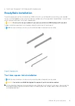
Страница 19: ...rate each rail assembly by sliding the inside rail out of the outside rail NOTE For more installation instructions see the installation labels attached to the rail assembly Figure 8 Separate rails Tool less square hole installation NOTE For more installation instructions see the installation labels attached to the rail assembly CAUTION Your switch is not NEBS Earthquake Z4 compliant if you this in...

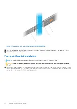
Страница 20: ...t installation NOTE For more installation instructions see the installation labels attached to the rail assembly CAUTION Your switch is not NEBS Earthquake Z4 compliant if you this installation method 1 For this configuration remove the castings from the front side of each ReadyRails assembly see item 1 Use a Torx screwdriver to remove the two screws from each front latch on the switch side of the...

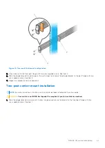
Страница 21: ...crews See item 3 4 Repeat this procedure for the second rail Two post center mount installation NOTE For more installation instructions see the installation labels attached to the rail assembly CAUTION Your switch is not NEBS Earthquake Z4 compliant if you this installation method 1 Slide the plunger bracket rearward until it clicks into place and secure the bracket to the front post flange with t...

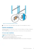
Страница 22: ...ee the installation labels attached to the rail assembly CAUTION To be NEBS Earthquake Z4 compliant you must remove the tool less latch castings described in Step 1 1 For this installation remove the tool less latch castings from the front side of each ReadyRails assembly See item 1 Use a Torx screwdriver to remove the two screws from each front latch on the switch side of the rail Remove the tool...

Страница 23: ...wo post configurations slide the switch into the rails in the same manner as the four post configurations 1U front rack installation Configure the rails that are attached to the switch NOTE For more instructions see the installation instruction labels on the rail 1 Attach the inner switch rails to the S5148F ON switch Line up the rail with the mounting heads and attach the rail to the switch Slide...

Страница 24: ...nted ReadyRails and slide the switch in until it is flush with front of rack To keep the switch from inadvertently sliding out of the rack and falling about 3 inches before you fully insert your switch the rail locking feature engages Figure 14 Front rack installation 24 S5148F ON switch installation ...

Страница 25: ... not included to the desired length The cable length must facilitate proper operation of the fault interrupt circuits Use the shortest cable route allowable 2 To attach the ground cable use one of the following Using one threaded M3 hole attached the ground cable to the lug using an M3 screw with a captive internal tooth lock washer Torque the screw to 4 5 in lbs Using one of the two M4 threaded h...

Страница 26: ...rder all other power cables separately NOTE ESD damage can occur if components are mishandled Always wear an ESD preventive wrist or heel ground strap when handling the S5148F ON switch and components Power up sequence When the switch powers up the fans immediately come on at high speed The fan speed slows as the switch continues to boot up After switch placement After you have securely installed ...

Страница 27: ...he software versions do not match upgrade the replacement switch software using the procedure included with the firmware download 7 Copy the backed up switch configuration to the new switch copy tftp hostip filepath running config 8 Install the new switch in your rack or cabinet For detailed installation instructions see S5148F ON switch installation If you are using the fan trays or PSUs from the...

Страница 28: ...a single PSU install a blank plate in the other PSU slot Use power supply 2 PSU2 as the blank plate slot To install the blank plate use a 1 Philips screw driver NOTE ESD damage can occur if components are mishandled Always wear an ESD preventive wrist or heel ground strap when handling the S5148F ON switch and components Topics Components AC or DC power supply installation DC power supply to power...

Страница 29: ...OTE If you use a single PSU install a blank plate in the other PSU slot If you are only using one power supply install the power supply in the first slot PSU1 Install a blank plate in the second slot PSU2 1 Remove the PSU slot cover from the S5148F ON switch using a small 1 Phillips screwdriver 2 Remove the PSU from the electro static bag 3 Insert the PSU into the switch PSU slot insert the expose...

Страница 30: ...nt PSU to slide it into the power supply bay 4 Attach the power cord to the replacement PSU NOTE The switch powers up when the cables are connected between the power supply and the power source DC power supply to power source connection Each DC powered switch comes with a set containing a prewired 3 inch 8 AWG power supply connector and a four screw wiring block One set is provided for each DC PSU...

Страница 31: ... hear the click of the power connector s left and right levered clamps lock into place WARNING Never try to force the power connector into or out of the DC PSU power socket NOTE To remove the power connector from a DC PSU use the orange tab on the side of the connector Doing so disengages the power connector s clamps After engaging the orange tab pull the power connector from the DC PSU socket Pow...

Страница 32: ...icator is the reverse airflow direction All fans and PSUs in a configuration must be in the same airflow direction Environmental factors can decrease the amount of time required between fan replacements Check the environmental factors regularly An increase in temperature and or particulate matter in the air might affect performance for example new equipment installation CAUTION Check the fans at s...

Страница 33: ...nts Check the environmental factors regularly An increase in temperature and or particulate matter in the air might affect performance CAUTION Check the fan air filters at six month intervals and replace them as necessary To accurately determine air filter replacement intervals regularly monitor the speeds of the cooling fans An increase in overall fan speed may indicate a clogged filter You must ...

Страница 34: ...needs the filter replaced 3 Slide the existing filter upwards to remove it from the module 4 Replace the filter with a new filter of the same size 5 Reinsert the fan module 6 Repeat for the remaining modules that need the filter replaced 34 Fans ...

Страница 35: ...5e or Cat6 Ethernet cables the maximum cable length is 100m However if the Ethernet cable is disconnected from the patch panel or terminal server but connected to the RJ45 console the maximum cable length is 6m If the cable is longer than 6m when disconnected from the panel or server your switch may not boot NOTE Before starting this procedure ensure that your PC has a 9 pin serial port and that y...

Страница 36: ... bits 1 stop bit No flow control USB storage mount USB storage does not automatically mount USB storage supports the FAT file system To use USB storage first mount the device using the following steps 1 Create a mount directory for the USB storage ONIE mkdir mnt usb 2 View the fixed disks using the fdisk command ONIE mnt fdisk l For internal storage Disk dev sda 15 8 GB 15829303296 bytes 255 heads...

Страница 37: ...stem Grub bootloader example GNU GRUB version 2 02 beta2 e4a1fe391 ONIE Install OS ONIE Rescue ONIE Uninstall OS ONIE Update ONIE ONIE Embed ONIE EDA DIAG Your switch comes with ONIE installed NOTE To access ONIE use the RJ 45 console port ONIE example ONIE Install OS For downloading and installing an OS from a URL Starts ONIE with ONIE Discovery Service factory default boot ONIE Rescue Starts ONI...

Страница 38: ...The ONIE Install environment uses DHCP to assign an IP address to the management interface eth0 If that fails it uses the default IP address 192 168 3 10 255 255 255 0 To display the IP address use the ifconfig eth0 command as shown ONIE ifconfig eth0 eth0 Link encap Ethernet HWaddr 90 B1 1C F4 9C 76 inet addr 10 11 53 33 Bcast 10 255 255 255 Mask 255 0 0 0 inet6 addr fe80 92b1 1cff fef4 9c76 64 S...

Страница 39: ...ve conformance statement Japan VCCI compliance for class A equipment Korean certification of compliance Safety standards and compliance agency certifications Electromagnetic compatibility Product recycling and disposal Chassis physical design Table 5 Chassis physical design Parameter Specifications Height 1 72 inches 44 mm Width 17 1 inches 434 mm Depth Chassis 18 2 inches 462 mm PSU fan tray hand...

Страница 40: ...ower requirements Parameter Specifications Power supply 100 240 VAC 50 60 Hz Maximum current draw per switch 4 7A 3 9A at 100 120V AC 2 35A 1 95A at 200 240V AC Maximum power capability 470 Watts Typical power consumption 200 Watts Table 8 DC power requirements Parameter Specifications Minimum maximum input voltage range 40 5 48V 60V Input power at full load 40 5V 460W 48V 930W 60V 950W without fa...

Страница 41: ... operate the equipment This device complies with Part 15 of the FCC Rules Operation is subject to the following two conditions 1 this device may not cause harmful interference and 2 this device must accept any interference received including interference that may cause undesired operation Figure 21 Canadian Department of Communication Statement European Union EMC directive conformance statement Th...

Страница 42: ...f this equipment is used in a domestic environment radio disturbance may arise When such trouble occurs the user may be required to take corrective actions NOTE Use the AC power cords with Dell EMC equipment only Do not use Dell EMC AC power cords with any unauthorized hardware Figure 23 Japan warning label Korean certification of compliance Figure 24 Korean certification of compliance Figure 25 K...

Страница 43: ... 2006 CISPR 32 Class A International CISPR 32 Class A EN55032 Japan VCCI V 3 2011 04 Class A Korea KN32 Class A Taiwan CNS13438 Class A USA FCC CFR47 Part 15 Subpart B Class A Immunity EN 300 386 v2 1 1 2016 07 EMC for Network Equipment EN 55024 A1 A2 EN 61000 3 2 Harmonic Current Emissions EN 61000 3 3 Voltage Fluctuations and Flicker EN 61000 4 2 ESD EN 61000 4 3 Radiated Immunity EN 61000 4 4 E...

Страница 44: ...quipment EEE is to be collected separately and to be reused recycled or recovered at end of life Users of EEE with the WEEE marking per Annex IV of the WEEE Directive as shown above must not dispose of end of life EEE as unsorted municipal waste but use the collection framework available to customers for the return recycling and recovery of WEEE Customer participation is important to minimize any ...

Страница 45: ... down to the bottom of the web page and select your country from the drop down menu To obtain product specific information enter the 7 character service tag known as a luggage tag or 11 digit express service code of your switch and click Submit To view the chassis service tag or express service code pull out the tag or enter the show chassis command from the CLI To receive more technical support c...

Отзывы: