


Dell EMC PowerStore Quick Start Guide
Page
4
of
8
4.
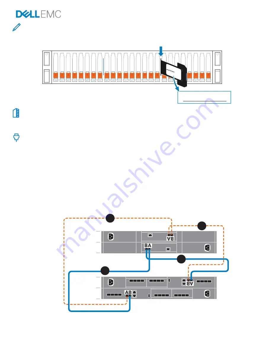
Record the Dell Service Tag
Locate and record the number from the black Dell Service Tag on the front of the base enclosure.
5.
Install optional expansion enclosures
*
For each additional expansion enclosure, repeat steps 2 and 3 to install the rails and expansion enclosure onto the rails.
If you are not installing an expansion enclosure, continue to step 7.
6.
Connect the expansion enclosure to the base enclosure
*
Before you begin
:
Select a single color of cable labels for use on all of the enclosures attached to the base enclosure (3 maximum). Apply cable
labels at each end of the following cables:
-
Node to first expansion enclosure
-
Node to last expansion enclosure
-
Expansion enclosure to expansion enclosure
Cable both embedded modules on the base enclosure to the link control card (LCC) on the new expansion enclosure:
1.
Connect node A, SAS port B to LCC A, port A on the expansion enclosure (1).
2.
Connect node B, SAS port B to LCC B, port A on the expansion enclosure (2).
3.
Connect node B, SAS port A to LCC A, port B on the expansion enclosure (3).
4.
Connect node A, SAS port A to LCC B, port B on the expansion enclosure (4).
If adding a second and third expansion enclosure, daisy chain the enclosures using the diagrams on the cable label sheet.
B
A
Node
B
A
Expansion
enclosure 1
4
1
3
2
*Not applicable for PowerStore 500T.
Dell Service Tag


