

3.
Connect the MGMT Ethernet cables to the two MGMT ports on each node.
a.
Connect the green cable labeled MGMT1 to the MGMT1 port as shown on the
port map. Repeat at each node.
b.
Connect the violet cable labeled MGMT2 to the MGMT2 port as shown on the
port map. Repeat at each node.
c.
Verify that the cables are securely latched at each node connection by pulling lightly on
the cable at each node connection.
4.
Connect the AC power cables to the power supply units on each node.
a.
Connect the black power cable to PSU1/the black ‘AC Power’ block on the port map.
b.
Connect the gray power cable to PSU2/the gray ‘AC Power’ block on the port map.
c.
Repeat at each node.
d.
Verify that the power cable routing allows each server node to move freely on the
slide rails.
CAUTION:
Loop the power cable and secure to the PSU handle with the provided
Velcro straps as shown in the following figure. Ensure the strap lifts the power
cable to prevent binding when server is extended during service.
4
Connect power cables to redundant utility power sources
Connect the black and the gray power cables to separate utility power feeds.
CAUTION:
Redundant power connections are required to maintain HA.
Ensure gray and black cords connect to separate power supplies.
1.
Connect the gray power cables to the utility A Power Distribution Unit (PDU).
2.
Connect the black power cables to the utility B PDU.
5
Check metro node interconnections and power
1.
Verify that each node is getting power from BOTH power zones. Verify that the PSU
handle glows solid GREEN for both PSUs in each node.
CAUTION:
If the PSU LED is OFF, check the power cable connections. If the
LED is not solid GREEN, see
PowerEdge R640
Installation and Service manual
(https://topics-cdn.dell.com/pdf/poweredge-r640_Owners-Manual_en-us.pdf)
for further PSU LED status information.
2.
Turn on both servers and check health status on the front left panel.
a.
Verify that power switch indicator is GREEN (right front).
b.
Verify that there are no AMBER health status indicator LEDs (left front).
Health Status
Power Switch
ID LED
3.
Verify that the LINK LED is ON solid GREEN for the MGMT1 and MGMT2 ports.
4.
Verify the LINK LEDs are ON solid GREEN for the LCOM1 and LCOM2 ports.
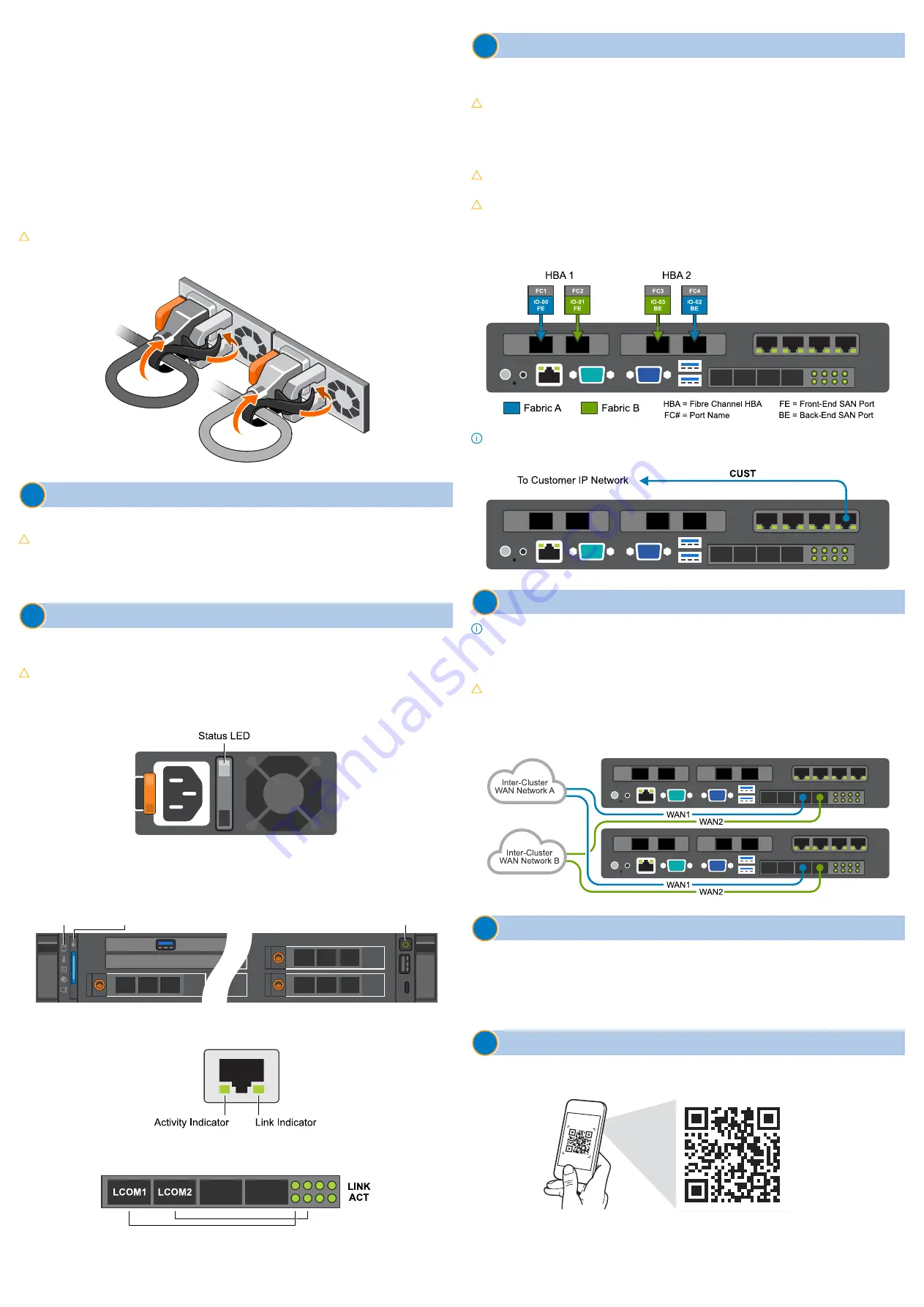
6
Establish local customer connections
For the following connections, route all cables through the CMA assembly to the side of the
cabinet. Secure the cables both in the CMA and at the side of the cabinet using Velcro straps.
CAUTION:
All node connections must route through the CMA assembly to
maintain HA during service operations. Provide adequate length to maintain arm
movement and cable health.
1.
Connect customer-supplied fibre-optic cables from the front-end and back-end SANs to
the appropriate metro node ports on both directors.
CAUTION:
To avoid damage or contamination, do not touch the ends of any
fibre-optic cable.
CAUTION:
Use redundant physical fibre channel links to connect each host to
the metro node directors, and each metro node director to the back-end storage.
To prevent data unavailability, ensure that each host in a storage view has paths
to both directors in the cluster, and that the multipathing configuration
distributes the paths evenly between directors A and B.
NOTE:
The fiber-optic connections on HBA2 are inverted as compared to HBA1.
2.
Connect metro node ‘CUST’ port to the customer IP network on both directors:
7
Establish metro customer connections
NOTE:
This section applies to dual cluster ‘metro’ system configurations only. Skip this
section for ‘local’ system configurations.
For the following connections, route all cables through the CMA assembly to the side of the
cabinet. Secure the cables both in the CMA and at the side of the cabinet using Velcro straps.
CAUTION:
All node connections must route through the CMA (mechanical arm)
to maintain HA during service operations.
1.
Connect the inter-cluster WAN IP connections. Ensure that each node or director has
two independent paths to each node or director in the other cluster. Metro node supports
Fibre IP WAN connections only.
8
Next steps
•
To configure the metro node, go to the SolVe Desktop or SolVe Online, then follow the
path
VPLEX Admin Procedures
→
Configure
→
Configure metro node
.
•
For additional service, maintenance, and troubleshooting information, either
download the SolVe Desktop from SupportZone or go to the SolVe Online
(
https://solveonline.emc.com/solve/home
i
Quick Resource Locator
To access the metro node additional documentation and videos, scan the Dell EMC QRL code
by using your smartphone.


