


Great user manuals database on
1.
If you are booting to a USB device, connect the USB device to a USB connector.
2.
Turn on (or restart) your computer.
3.
When
F2 = Setup, F12 = Boot Menu
appears in the upper-right corner of the screen, press <F12>.
If you wait too long and the operating system logo appears, continue to wait until you see the Microsoft Windows desktop. Then shut down your
computer and try again.
The
Boot Device Menu
appears, listing all available boot devices. Each device has a number next to it.
4.
At the bottom of the menu, enter the number of the device that is to be used for the current boot only.
For example, if you are booting to a USB memory key, highlight
USB Flash Device
and press <Enter>.
Changing Boot Sequence for Future Boots
1.
2.
Use the arrow keys to highlight the
Boot Sequence
menu option and press <Enter> to access the menu.
3.
Press the up- and down-arrow keys to move through the list of devices.
4.
Press the spacebar to enable or disable a device (enabled devices have a checkmark).
5.
Press plus (+) or minus (
–
) to move a selected device up or down the list.
Clearing Forgotten Passwords
1.
2.
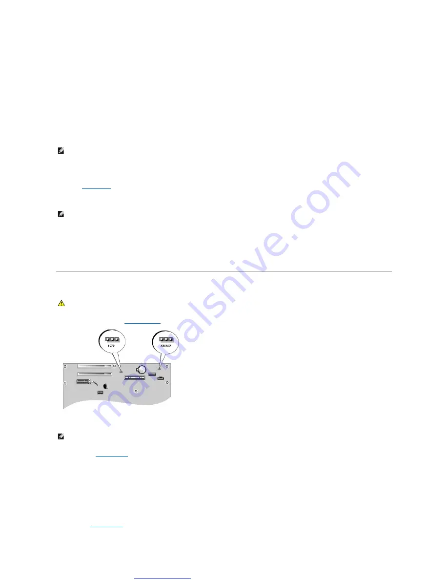
Locate the 3-pin password jumper (PSWD) on the system board, and attach the jumper plug to pins 2 and 3 to clear the password.
3.
Replace the
.
4.
Connect your computer and monitor to electrical outlets, and turn them on.
5.
After the Microsoft
®
Windows
®
desktop appears on your computer, shut down the computer.
6.
Turn off the monitor and disconnect it from the electrical outlet.
7.
Disconnect the computer power cable from the electrical outlet, and press the power button to ground the system board.
8.
NOTE:
To boot to a USB device, the device must be bootable. To make sure your device is bootable, check the device documentation.
NOTE:
Write down your current boot sequence in case you want to restore it.
CAUTION:
Before you begin any of the procedures in this section, follow the safety instructions located in the Product Information Guide.
NOTE:
When you receive your computer, the jumper plug is attached to pin 1.


