background image


8


8


3.


Wiring connectivity diagram


All cables are Wire except Item 

“C” is FFC cable.


Содержание D7523QTc

Страница 1: ...ral Power Safety 4 2 Exploded view diagram with list of items 5 3 Wiring connectivity diagram 8 4 How to connect and disconnect power cable connectivity cable 9 5 Mechanical Instruction 11 5 1 Disassembly Procedures 12 5 2 Assembly Procedures 18 6 Trouble shooting instructions 22 Model No D7523QT Regulatory model D7523QTc ...

Страница 2: ...ecalculated or preheated air NOTE Review the weight limits referenced in your computer documentation before placing a monitor or other devices on top of your computer Ensure that nothing rests on your equipment s cables and that the cables are not located where they can be stepped on or tripped over Ensure that all cables are connected to the appropriate connectors Some connectors have a similar a...

Страница 3: ... may build up on your body or an object such as a peripheral and then discharge into another object such as your computer To prevent ESD damage you should discharge static electricity from your body before you interact with any of your equipment s internal electronic components such as a memory module You can protect against ESD by touching a metal grounded object such as an unpainted metal surfac...

Страница 4: ... as risk of electric shock and or fire Ensure that the ground prong of the power plug is inserted into the mating ground contact of the power strip Be sure to grasp the plug not the cable when disconnecting equipment from an electric socket If your equipment uses an AC adapter Use only the Dell provided AC adapter approved for use with this device Use of another AC adapter may cause a fire or expl...

Страница 5: ... 5 5 2 Exploded view diagram with list of items 36 35 34 37 ...

Страница 6: ...D 1 14 KEY BOARD 1 15 SUB BOARD 1 16 INSULATING SHEET 400 298 0 43 1 17 CONNECTOR BOARD 1 18 BKT_SPEAKER L 2 19 BKT_SPEAKER R 2 20 BKT_KEY_COVER 1 21 BASE_BTM P75 Daoc3 1 22 BKT_BATTERY 2 23 MAGNET 28 10 4 NdFeB 340 20mT 4 24 Cover_IO P75 Daoc3 1 25 BKT_OPS_CHASSIS 2 26 BKT_OPS_CHASSIS 1 27 WIRE CLIP 6 28 RUBBER PAD 2 29 BKT_IO_SIDE 1 30 BKT_IO_BTM 1 31 BKT_TOP 1 32 INSULATING SHEET 148 19 5 0 62 ...

Страница 7: ...tps www dell com support 2 Verify your country or region in the Choose A Country Region drop down menu at the bottom right corner of the page 3 Click Contact Us next to the country dropdown 4 Select the appropriate service or support link based on your need 5 Choose the method of contacting Dell that is convenient for you ...

Страница 8: ... 8 8 3 Wiring connectivity diagram All cables are Wire except Item C is FFC cable ...

Страница 9: ... 9 9 4 How to connect and disconnect power cable connectivity cable ...

Страница 10: ... 10 10 ...

Страница 11: ...Dell will deem warranty void if any disassembly is done on the monitors Tools Required List the type and size of the tools that would typically can be used to disassemble the product to a point where components and materials requiring selective treatment can be removed Tool Description Screwdriver Phillip head Hexagonal head Penknife ...

Страница 12: ...e EPS TOP and accessories PE bag remote control and battery AA 2 stylus 2pcs Power cable varies by contries HDMI 2 0 cable DP 1 2 cable USB 3 1 Gen 1 upstream cable Wire Saddle 5 pcs and QSG S2 Remove the desiccants Take out 4pcs desiccant from the bag Use a machine jip to take out the whole monitor from EPS bottom Remove the PE bag from top to bottom and put the monitor on ESD protection foam Des...

Страница 13: ...emove 8 screws for remove the DIE CASTING No 1 8 screw size M4x10 Torque 12 2kgf cm Use a Philips head screwdriver to remove 17 screws for remove the Rear Cover No 1 17 screw size P3x6 Torque 6 1kgf cm Use a Philips head screwdriver to remove 33 screws for remove the Rear Cover No 1 33 screw size M4x6 Torque 6 1kgf cm No 1 2 screw size M3x10 Torque 6 1kgf cm ...

Страница 14: ...ain board Power board OPS board Converter board etc Use a Philips head screwdriver to remove 29 screws for remove the Main board Power board OPS board Converter board No 1 23 screw size M3x8 Torque 4 1kgf cm No 24 28 screw size M4x6 Torque 6 1kgf cm No 29 screw size M4x6 Torque 6 1kgf cm ...

Страница 15: ...ain board Power board OPS board Converter board etc Use a Philips head screwdriver to remove 29 screws for remove the Main board Power board OPS board Converter board No 1 23 screw size M3x8 Torque 4 1kgf cm No 24 28 screw size M4x6 Torque 6 1kgf cm No 29 screw size M4x6 Torque 6 1kgf cm ...

Страница 16: ...ove 5 screws for remove the BKT No 1 4 screw size M3x4 Torque 4 1kgf cm No 5 screw size M4x6 Torque 4 1kgf cm S8 Remove the Speakers I O board Key board Use a Philips head screwdriver to remove 18 screws of speakrers I O board key board No 1 18 screw size M3x8 Torque 4 1kgf cm Use a Philips head screwdriver to remove 10 screws for remove the Key board No 1 4 screw size M3x6 Torque 4 1kgf cm No 5 6...

Страница 17: ... 17 17 No 1 4 screw size M3x6 Torque 4 1kgf cm S9 Remove the Speaker BKT Use a Philips head screwdriver to remove 4 screws for remove the Speaker BKT No 1 4 screw size M4x5 Torque 6 1kgf cm ...

Страница 18: ...6 1kgf cm S2 Assembly the Speakers Key board and I O board Use a Philips head screwdriver to screw 10 screws for tighten the Key board and I O board No 1 4 screw size M3x6 Torque 4 1kgf cm No 5 6 screw size M3x6 Torque 4 1kgf cm No 1 4 screw size M3x6 Torque 4 1kgf cm Use a Philips head screwdriver to remove 18 screws of speakrers I O board BKT No 1 18 screw size M3x8 Torque 4 1kgf cm ...

Страница 19: ...ard etc Use a hexagonal screwdriver to screw 7 screws No 1 2 hex screw size M3x8 Torque 4 1kgf cm No 3 5 hex screw size M3x5 Torque 4 1kgf cm No 6 7 screw Torque 4 5 0 5kgf cm Use a Philips head screwdriver to screw 29 screws for tighten the Main board Power board OPS board Converter board etc No 1 23 screw size M3x8 Torque 4 1kgf cm No 24 28 screw size M4x6 Torque 6 1kgf cm No 29 screw size M4x6 ...

Страница 20: ...or tighten the Rear Cover No 1 17 screw size P3x6 Torque 6 1kgf cm Use a Philips head screwdriver to screw 33screws for tighten the Rear Cover No 1 33 screw size M4x6 Torque 6 1kgf cm No 1 2 screw size M3x10 Torque 6 1kgf cm Use a Philips head screwdriver to screw 8 screws for tighten the DIE CASTING No 1 8 screw size M4x10 Torque 12 2kgf cm ...

Страница 21: ...e_Buckles and carton Put the EPS TOP and accessories PE bag into the carton Assemble 6 pcs of Package_Buckles and seal the carton with tapes Accessories PE bag remote control and battery AA 2 stylus 2pc s Power cable varies by contries HDMI2 0 cable DP 1 2 cable USB3 1 Gen 1 upstream cable Wire Saddle 5 pcs and QSG ...

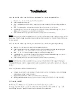
Страница 22: ... 22 22 6 Trouble shooting instructions ...

Страница 23: ... 23 23 ...

Страница 24: ... 24 24 ...

Страница 25: ... 25 25 ...

Страница 26: ... 26 26 ...

Страница 27: ... 27 27 ...

Отзывы: