background image

Steps

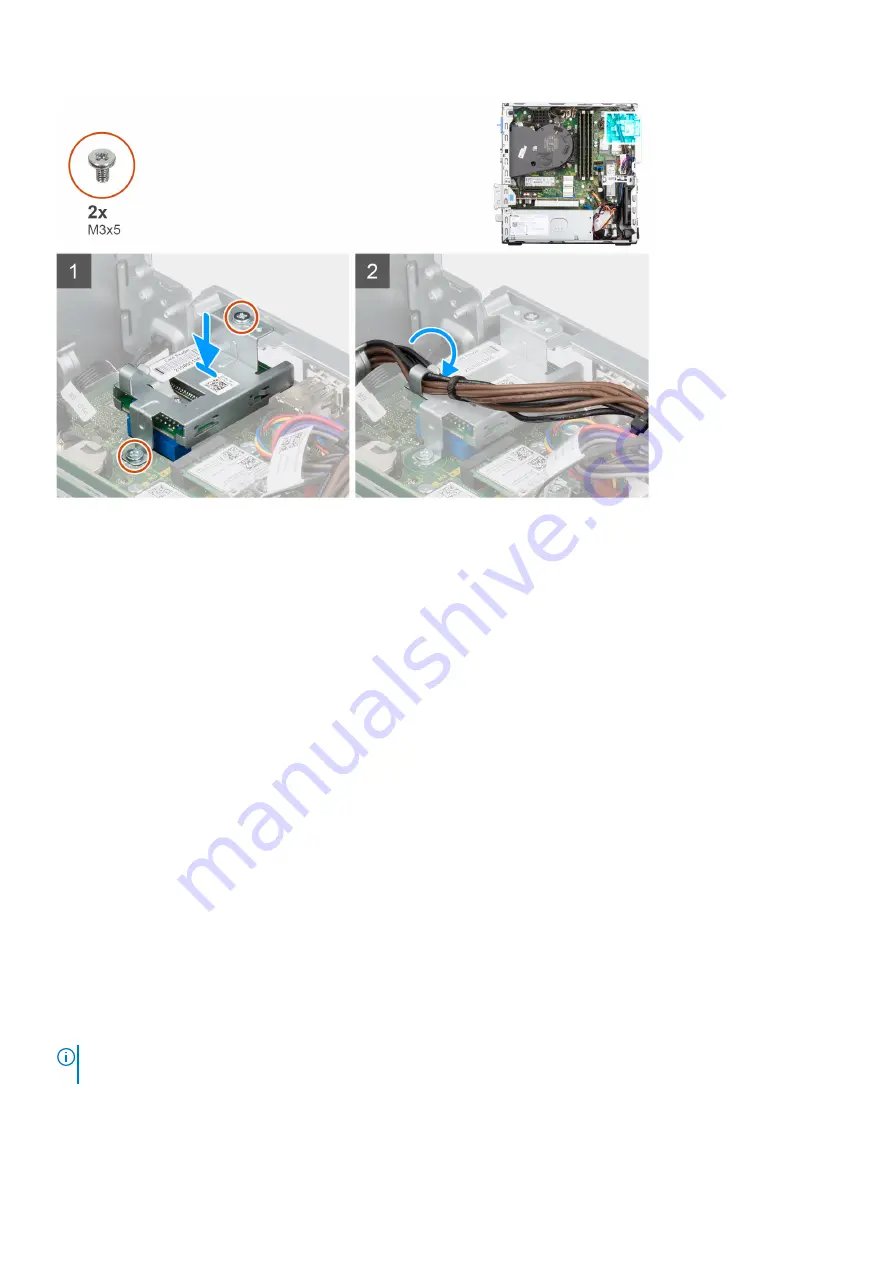
1. Place and align the screw holes on the SD-card reader to the screw holes on the chassis.
2. Connect the SD-card reader to the connector on the system board.
3. Replace the two screws (M3x5) that secure the SD-card bracket to the system board and the chassis.
4. Route the power-supply cables through the routing guides on the SD-card reader bracket.

Next steps

1. Install the 

hard-drive and optical-drive cage

.

2. Install the 

3.5-inch hard-drive

.

3. Install the 

2.5-inch hard-drive

.

4. Install the 

front bezel

.

5. Install the 

side cover

.

6. Follow the procedure in 

after working inside your computer

.

Coin-cell battery

Removing the coin-cell battery

Prerequisites

1. Follow the procedure in 

before working inside your computer

.

2. Remove the 

side cover

.

3. Remove the 

2.5-inch hard-drive

.

4. Remove the 

3.5-inch hard-drive

.

5. Remove the 

hard-drive and optical-drive bracket

.

NOTE:

 Removing the coin-cell battery resets the BIOS setup program settings to default. It is recommended that you note

the BIOS setup program settings before removing the coin-cell battery.

About this task

The following images indicate the location of the coin-cell battery and provide a visual representation of the removal procedure.

40

Removing and installing components

Содержание D17S

Страница 1: ...OptiPlex 7000 Small Form Factor Service Manual Regulatory Model D17S Regulatory Type D17S001 March 2022 Rev A00 ...

Страница 2: ...tial damage to hardware or loss of data and tells you how to avoid the problem WARNING A WARNING indicates a potential for property damage personal injury or death 2021 2022 Dell Inc or its subsidiaries All rights reserved Dell EMC and other trademarks are trademarks of Dell Inc or its subsidiaries Other trademarks may be trademarks of their respective owners ...

Страница 3: ...stalling the intrusion switch 18 Hard drive 19 Removing the 2 5 inch hard drive 19 Installing the 2 5 inch hard drive 21 Removing the 3 5 inch hard drive 23 Installing the 3 5 inch hard drive 25 Hard drive and optical drive bracket 26 Removing the hard drive and optical drive bracket 26 Installing the hard drive and optical drive bracket 27 Optical drive 29 Removing the optical drive 29 Installing...

Страница 4: ...ssembly 53 Voltage regulator heat sink 54 Removing the voltage regulator heat sink 54 Installing the voltage regulator heat sink 55 Processor 56 Removing the processor 56 Installing the processor 57 Expansion card 58 Removing the graphics card 58 Installing the graphics card 59 Optional I O modules PS2 Serial 60 Removing optional PS2 module 60 Installing optional PS2 module 62 Optional I O modules...

Страница 5: ...the USB drive in Windows 99 Updating the BIOS from the F12 One Time boot menu 99 System and setup password 100 Assigning a system setup password 100 Deleting or changing an existing system setup password 101 Clearing CMOS settings 101 Clearing BIOS System Setup and System passwords 101 Chapter 5 Troubleshooting 102 Dell SupportAssist Pre boot System Performance Check diagnostics 102 Running the Su...

Страница 6: ...ructions that is shipped with the product or at www dell com regulatory_compliance CAUTION Before touching anything inside your computer ground yourself by touching an unpainted metal surface such as the metal at the back of the computer While you work periodically touch an unpainted metal surface to dissipate static electricity which could harm internal components CAUTION When you disconnect a ca...

Страница 7: ... done through the use of a field service electrostatic discharge ESD kit When connecting a bonding wire ensure that it is connected to bare metal and never to a painted or non metal surface The wrist strap should be secure and in full contact with your skin and ensure that you remove all jewelry such as watches bracelets or rings prior to bonding yourself and the equipment Electrostatic discharge ...

Страница 8: ...ecommended to test the wrist strap and bonding wire at least once per week ESD Wrist Strap Tester The wires inside of an ESD strap are prone to damage over time When using an unmonitored kit it is a best practice to regularly test the strap prior to each service call and at a minimum test once per week A wrist strap tester is the best method for doing this test If you do not have your own wrist st...

Страница 9: ...t apart for a stable base and point your toes out 2 Tighten stomach muscles Abdominal muscles support your spine when you lift offsetting the force of the load 3 Lift with your legs not your back 4 Keep the load close The closer it is to your spine the less force it exerts on your back 5 Keep your back upright whether lifting or setting down the load Do not add the weight of your body to the load ...

Страница 10: ... box This is to ensure that the correct number of screws and correct screw type is restored when the component is replaced NOTE Some computers have magnetic surfaces Ensure that the screws are not left attached to such surfaces when replacing a component NOTE Screw color may vary with the configuration ordered Table 1 Screw list Component Screw type Quantity Screw image Solid state drive M2x3 1 Ha...

Страница 11: ...FRU list OptiPlex 7000 Small Form Factor CRU component FRU component Side cover Front bezel Intrusion switch 2 5 inch hard drive 3 5 inch hard drive Optical drive Hard drive and optical drive bracket Hard drive and optical drive supporting bracket M 2 Solid state drive WLAN card Memory module Expansion card Heat sink and fan assembly Removing and installing components 11 ...

Страница 12: ... Optional I O module PS2 Serial Coin cell battery System fan Speaker VR heat sink Power button Power supply unit Processor System board Major components of OptiPlex 7000 Small Form Factor The following image shows the major components of OptiPlex 7000 Small Form Factor 12 Removing and installing components ...

Страница 13: ...Removing and installing components 13 ...

Страница 14: ...ding to warranty coverages purchased by the customer Contact your Dell sales representative for purchase options Side cover Removing the side cover Prerequisites 1 Follow the procedure in before working inside your computer NOTE Ensure that you remove the security cable from the security cable slot if applicable About this task The following images indicate the location of the side cover and provi...

Страница 15: ... side cover with the slots on the chassis 2 Slide the side cover towards the front of the computer until you hear the release latch click Next steps 1 Follow the procedure in after working inside your computer Front bezel Removing the front bezel Prerequisites 1 Follow the procedure in before working inside your computer 2 Remove the side cover About this task The following images indicate the loc...

Страница 16: ...the front bezel Installing the front bezel Prerequisites If you are replacing a component remove the existing component before performing the installation procedure About this task The following images indicates the location of the front bezel and provide a visual representation of the installation procedure 16 Removing and installing components ...

Страница 17: ...llow the procedure in after working inside your computer Intrusion switch Removing the intrusion switch Prerequisites 1 Follow the procedure in before working inside your computer 2 Remove the side cover About this task The following images indicate the location of the intrusion switch and provide a visual representation of the removal procedure Removing and installing components 17 ...

Страница 18: ...uter Installing the intrusion switch Prerequisites If you are replacing a component remove the existing component before performing the installation procedure About this task The following images indicate the location of the intrusion switch and provide a visual representation of the installation procedure 18 Removing and installing components ...

Страница 19: ...ector on the system board Next steps 1 Install the side cover 2 Follow the procedure in after working inside your computer Hard drive Removing the 2 5 inch hard drive Prerequisites 1 Follow the procedure in before working inside your computer 2 Remove the side cover 3 Remove the front bezel Removing and installing components 19 ...

Страница 20: ...About this task The following images indicate the location of the 2 5 inch hard drive and provide a visual representation of the removal procedure 20 Removing and installing components ...

Страница 21: ...racket 4 Pry the hard drive carrier to release the 2 5 inch hard drive from the mounting points on the hard drive carrier 5 Slide and lift the 2 5 inch hard drive off the hard drive carrier Installing the 2 5 inch hard drive Prerequisites If you are replacing a component remove the existing component before performing the installation procedure About this task The following images indicate the loc...

Страница 22: ...22 Removing and installing components ...

Страница 23: ...Use the arrows seen on the caddy as guides to identify the tabs on the tray 5 Connect the hard drive data and power cables to the connectors on the hard drive Next steps 1 Install the front bezel 2 Install the side cover 3 Follow the procedure in after working inside your computer Removing the 3 5 inch hard drive Prerequisites 1 Follow the procedure in before working inside your computer 2 Remove ...

Страница 24: ... lift the hard drive carrier 3 Slide the hard drive carrier away from the chassis and lift hard drive carrier out of the disk drive cage 4 Pry the hard drive carrier to release the mounting points on the carrier from the slots on the 3 5 inch hard drive 5 Lift the 3 5 inch hard drive off the hard drive carrier 24 Removing and installing components ...

Страница 25: ...component remove the existing component before performing the installation procedure About this task The following images indicate the location of the 3 5 inch hard drive and provide a visual representation of the installation procedure Removing and installing components 25 ...

Страница 26: ...abs on the tray 4 Connect the hard drive data and power cables to the connectors on the hard drive Next steps 1 Install the front bezel 2 Install the side cover 3 Follow the procedure in after working inside your computer Hard drive and optical drive bracket Removing the hard drive and optical drive bracket Prerequisites 1 Follow the procedure in before working inside your computer 2 Remove the si...

Страница 27: ... locking mechanism towards the left to unlock the bracket and detach it from the chassis 4 Hold the lock handle to lift the bracket 5 Lift the bracket upwards and detach it from the mounting points on the top portion of the chassis 6 Disconnect the power and SATA cables from the optical drive and lift the bracket away from the computer Installing the hard drive and optical drive bracket Prerequisi...

Страница 28: ...ush the bracket until the assembly is secured onto the chassis 4 Move the lock handle from the locking mechanism towards the right to lock the bracket in place 5 Route the optical drive s power and data cables through the routing guide on the bracket 6 Route the hard drive power and SATA cables through the routing guide on the lock Next steps 1 Install the 3 5 inch hard drive 2 Install the 2 5 inc...

Страница 29: ...ove the side cover 3 Remove the front bezel 4 Remove the 2 5 inch hard drive 5 Remove the 3 5 inch hard drive 6 Remove the hard drive and optical drive bracket About this task The following images show the slim optical drive and provide a visual representation of the removal procedure Removing and installing components 29 ...

Страница 30: ...Steps 1 Press the tab on the optical drive to release the optical drive from the hard drive and optical drive bracket 30 Removing and installing components ...

Страница 31: ...cal drive Prerequisites If you are replacing a component remove the existing component before performing the installation procedure About this task The following images show the optical drive and provide a visual representation of the installation procedure Removing and installing components 31 ...

Страница 32: ...Steps Slide the optical drive into the hard drive and optical drive bracket until it snaps into place 32 Removing and installing components ...

Страница 33: ...g inside your computer 2 Remove the side cover 3 Remove the front bezel 4 Remove the 2 5 inch hard drive 5 Remove the 3 5 inch hard drive 6 Remove the hard drive and optical drive cage About this task The following images indicate the location of the M 2 2230 solid state drive and provide a visual representation of the removal procedure Steps 1 Remove the single M2x3 screw that secures the solid s...

Страница 34: ... slot on the system board 2 Slide the 2230 solid state drive into the M 2 card slot on the system board Replace the screw M2x3 that secures the 2230 solid state drive to the system board Next steps 1 Install the hard drive and optical drive bracket 2 Install the 3 5 inch hard drive 3 Install the 2 5 inch hard drive 4 Install the front bezel 5 Install the side cover 6 Follow the procedure in after ...

Страница 35: ...x3 screw that secures the 2280 solid state drive to the system board 2 Slide and lift the 2280 solid state drive from the M 2 card slot on the system board Installing the M 2 2280 solid state drive Prerequisites If you are replacing a component remove the existing component before performing the installation procedure About this task The following images indicates the location of the M 2 2280 soli...

Страница 36: ... bracket 2 Install the 3 5 inch hard drive 3 Install the 2 5 inch hard drive 4 Install the front bezel 5 Install the side cover 6 Follow the procedure in after working inside your computer Hard drive and optical drive supporting bracket Removing the hard drive and optical drive supporting bracket Prerequisites 1 Follow the procedure in before working inside your computer 2 Remove the side cover 3 ...

Страница 37: ... the bracket to free it from the front side of the chassis 3 Lift and remove the bracket from the system Installing the hard drive and optical drive supporting bracket Prerequisites If you are replacing a component remove the existing component before performing the installation procedure About this task The following images indicate the location of the hard drive and optical drive supporting brac...

Страница 38: ... inch hard drive 4 Install the front bezel 5 Install the side cover 6 Follow the procedure in after working inside your computer SD card reader Removing the SD card reader Prerequisites 1 Follow the procedure in before working inside your computer 2 Remove the side cover 3 Remove the front bezel 4 Remove the 2 5 inch hard drive 5 Remove the 3 5 inch hard drive 6 Remove the hard drive and optical d...

Страница 39: ... to the system board and the chassis 3 Disconnect the SD card reader from the connector on the system board 4 Lift and remove the SD card reader from the system Installing the SD card reader Prerequisites If you are replacing a component remove the existing component before performing the installation procedure About this task The following images indicate the location of the SD card reader and pr...

Страница 40: ... the side cover 6 Follow the procedure in after working inside your computer Coin cell battery Removing the coin cell battery Prerequisites 1 Follow the procedure in before working inside your computer 2 Remove the side cover 3 Remove the 2 5 inch hard drive 4 Remove the 3 5 inch hard drive 5 Remove the hard drive and optical drive bracket NOTE Removing the coin cell battery resets the BIOS setup ...

Страница 41: ...ll battery Installing the coin cell battery Prerequisites If you are replacing a component remove the existing component before performing the installation procedure About this task The following image indicates the location of the coin cell battery and provides a visual representation of the installation procedure Removing and installing components 41 ...

Страница 42: ...edure in after working inside your computer Power button Removing the power button Prerequisites 1 Follow the procedure in before working inside your computer 2 Remove the side cover 3 Remove the front bezel 4 Remove the 2 5 inch hard drive 5 Remove the 3 5 inch hard drive 6 Remove the hard drive and optical drive cage About this task The following images indicate the location of the power button ...

Страница 43: ...he power button and its cable from the from the slot on the chassis Installing the power button Prerequisites If you are replacing a component remove the existing component before performing the installation procedure About this task The following images indicate the location of the power button and provide a visual representation of the installation procedure Removing and installing components 43...

Страница 44: ...ptical drive cage 2 Install the 3 5 inch hard drive 3 Install the 2 5 inch hard drive 4 Install the front bezel 5 Install the side cover 6 Follow the procedure in after working inside your computer WLAN card Removing the WLAN card Prerequisites 1 Follow the procedure in before working inside your computer 2 Remove the side cover 3 Remove the front bezel 4 Remove the 2 5 inch hard drive 5 Remove th...

Страница 45: ... card bracket off the wireless card 3 Disconnect the antenna cables from the wireless card 4 Slide and remove the wireless card at an angle from the wireless card slot Installing the WLAN card Prerequisites If you are replacing a component remove the existing component before performing the installation procedure About this task The following image indicates the location of the wireless card and p...

Страница 46: ...d bracket on the wireless card 3 Align the notch on the wireless card with the tab on the wireless card slot 4 Slide the wireless card at an angle into the wireless card slot 5 Replace the screw M2x3 that secures the wireless card to the system board Next steps 1 Install the hard drive and optical drive cage 2 Install the 3 5 inch hard drive 3 Install the 2 5 inch hard drive 4 Install the front be...

Страница 47: ...ask The following images indicate the location of the internal WLAN antenna and provide a visual representation of the removal procedure Steps 1 Remove the antenna cables from the routing guides on the chassis 2 Remove the two M2x3 screws that secures the WLAN antenna to the chassis 3 Lift and remove the WLAN antenna from the chassis Installing the WLAN antenna Prerequisites If you are replacing a...

Страница 48: ...cure the WLAN antenna to the chassis Next steps 1 Install the hard drive and optical drive cage 2 Install the WLAN card 3 Install the 3 5 inch hard drive 4 Install the 2 5 inch hard drive 5 Install the front bezel 6 Install the side cover 7 Follow the procedure in after working inside your computer WLAN antennas External Removing the external WLAN antenna Prerequisites 1 Follow the procedure in be...

Страница 49: ... the external WLAN antennas and provide a visual representation of the removal procedure Steps 1 Remove the nut and washer from the two antenna heads 2 Gently pry and remove the antenna heads from the chassis 3 Remove the antenna cables from routing point on the system board 4 Lift and remove the antenna module from the system Removing and installing components 49 ...

Страница 50: ...crewdriver NOTE This step is only applicable when the system is being upgraded to have an external WLAN antenna 2 Route the antenna cables through the routing guides on the system board 3 Push the antenna modules in to the slot on the back panel of the chassis 4 Install the nut and washer to secure the antenna modules to the chassis Next steps 1 Install the hard drive and optical drive cage 2 Inst...

Страница 51: ... securing clips on each end of the memory module slot 2 Grasp the memory module near the securing clip and then gently ease the memory module out of the memory module slot CAUTION To prevent damage to the memory module hold the memory module by the edges Do not touch the components on the memory module NOTE Repeat step 1 to step 2 to remove any other memory modules installed in your computer NOTE ...

Страница 52: ...to step 3 when installing more than one memory module in your computer Next steps 1 Install the hard drive and optical drive cage 2 Install the 3 5 inch hard drive 3 Install the 2 5 inch hard drive 4 Install the side cover 5 Follow the procedure in after working inside your computer Processor fan and heat sink assembly Removing the processor fan and heat sink assembly Prerequisites 1 Follow the pr...

Страница 53: ...nd heat sink assembly to the system board 3 Lift the processor fan and heat sink assembly from the chassis Installing the processor fan and heat sink assembly Prerequisites If you are replacing a component remove the existing component before performing the installation procedure About this task The following image indicates the location of the processor fan and heat sink assembly and provides a v...

Страница 54: ...t steps 1 Install the hard drive and optical drive bracket 2 Install the front bezel 3 Install the side cover 4 Follow the procedure in after working inside your computer Voltage regulator heat sink Removing the voltage regulator heat sink Prerequisites 1 Follow the procedure in before working inside your computer WARNING The heat sink may become hot during normal operation Allow sufficient time f...

Страница 55: ... removal procedure Steps 1 Loosen the four captive screws that secure the voltage regulator heat sink to the system board 2 Lift the voltage regulator heat sink off the system board Installing the voltage regulator heat sink Prerequisites If you are replacing a component remove the existing component before performing the installation procedure About this task The following image indicates the loc...

Страница 56: ...our computer Processor Removing the processor Prerequisites 1 Follow the procedure in before working inside your computer 2 Remove the side cover 3 Remove the 2 5 inch hard drive 4 Remove the 3 5 inch hard drive 5 Remove the heat sink and fan assembly NOTE The processor may become hot during normal operation Allow sufficient time for the heat sink to cool before you touch it About this task The fo...

Страница 57: ...ide the socket or allow any objects to fall on the pins in the socket 3 Gently lift the processor from the processor socket Installing the processor Prerequisites If you are replacing a component remove the existing component before performing the installation procedure About this task The following image indicates the location of the processor and provides a visual representation of the installat...

Страница 58: ...processor are higher than the others the processor is not seated properly 3 When the processor is fully seated in the socket pivot the release lever down and place it under the tab on the processor cover Next steps 1 Install the heat sink and fan assembly 2 Install the 3 5 inch hard drive 3 Install the 2 5 inch hard drive 4 Install the front bezel 5 Install the side cover 6 Follow the procedure in...

Страница 59: ...he graphics card off the system board Installing the graphics card Prerequisites If you are replacing a component remove the existing component before performing the installation procedure About this task The following image indicates the location of the graphics card and provides a visual representation of the installation procedure Removing and installing components 59 ...

Страница 60: ... down firmly Ensure that the card is firmly seated 3 Close the PCIe door Next steps 1 Install the side cover 2 Follow the procedure in after working inside your computer Optional I O modules PS2 Serial Removing optional PS2 module Prerequisites 1 Follow the procedure in before working inside your computer 2 Remove the side cover 60 Removing and installing components ...

Страница 61: ...n assembly About this task The following images indicate the location of the optional PS2 module and provides a visual representation of the removal procedure Steps 1 Lift the pull tab and open the expansion card door Removing and installing components 61 ...

Страница 62: ...tional PS2 module Prerequisites If you are replacing a component remove the existing component before performing the installation procedure About this task The following images indicate the location of the optional PS2 module and provide a visual representation of the installation procedure 62 Removing and installing components ...

Страница 63: ... the chassis 2 Connect the PS2 cable to the connector on the system board 3 Close the expansion card door and press until it clicks into place Next steps 1 Install the heat sink and fan assembly 2 Install the side cover Removing and installing components 63 ...

Страница 64: ... of the optional I O module and provides a visual representation of the removal procedure NOTE The removal procedure for the VGA DP HDMI USB Type C optional I O modules are the same Steps 1 Remove the two screws that secure the I O module to the chassis 2 Disconnect the I O module cable from the connector on the system board 3 Remove the I O module from the computer Installing optional I O module ...

Страница 65: ...le for the first time 2 Connect the I O module cable to the connector on the system board 3 Insert the optional I O module into its slot on the chassis 4 Install the two screws to secure the I O module to the chassis Next steps 1 Install the heat sink and fan assembly 2 Install the side cover 3 Follow the procedure in after working inside your computer Chassis fan Removing the chassis fan Prerequi...

Страница 66: ...s 1 Disconnect the chassis fan cable from the connector on the system board 2 Gently pull the rubber grommets to release the fan from the chassis 3 Remove the fan off the chassis Installing the chassis fan Prerequisites If you are replacing a component remove the existing component before performing the installation procedure About this task The following image indicates the location of the chassi...

Страница 67: ...the hard drive and optical drive bracket 2 Install the 3 5 inch hard drive 3 Install the 2 5 inch hard drive 4 Install the front bezel 5 Install the side cover 6 Follow the procedure in after working inside your computer Speakers Removing the speaker Prerequisites 1 Follow the procedure in before working inside your computer 2 Remove the side cover About this task The following images indicate the...

Страница 68: ...ble from the connector on the system board 2 Unroute the speaker cable from the routing guides on the chassis 3 Press the tab and slide the speaker along with the cable from the slot on the chassis 68 Removing and installing components ...

Страница 69: ... into place 2 Route the speaker cable through the routing guide on the chassis 3 Connect the speaker cable to the connector on the system board Next steps 1 Install the side cover 2 Follow the procedure in after working inside your computer Power supply unit Removing the power supply unit Prerequisites 1 Follow the procedure in before working inside your computer 2 Remove the side cover 3 Remove t...

Страница 70: ...he chassis 3 Remove the three screws M6 32 that secure the power supply unit to the chassis 4 Slide and lift the power supply unit off the chassis Installing the power supply unit Prerequisites If you are replacing a component remove the existing component before performing the installation procedure About this task The following image indicates the location of the power supply unit and provides a...

Страница 71: ...ply cables through the routing guides on the chassis 4 Connect the power supply cables to the connectors on the system board Next steps 1 Install the hard drive and optical drive cage 2 Install the 3 5 inch hard drive 3 Install the 2 5 inch hard drive 4 Install the front bezel 5 Install the side cover 6 Follow the procedure in after working inside your computer Removing and installing components 7...

Страница 72: ...Coin cell battery socket 6 Power button cable 7 SD card reader slot 8 M 2 WLAN slot 9 Hard drive data cable SATA 0 10 M 2 2230 solid state drive slot 11 M 2 2230 2280 solid state drive slot 12 Chassis fan cable 13 ATX system power connector 14 Internal speaker cable slot 15 Hard drive data cable SATA 1 16 Optical drive hard drive data cable SATA 2 17 SATA power cable 18 a PCIe x16 slot SLOT 2 b PC...

Страница 73: ...h hard drive 5 Remove the 3 5 inch hard drive 6 Remove the hard drive and optical drive cage 7 Remove the expansion card 8 Remove the solid state drive 9 Remove the WLAN card 10 Remove the heat sink and fan assembly 11 Remove the memory modules 12 Remove the processor About this task The following images indicate the location of the system board and provide a visual representation of the removal p...

Страница 74: ...74 Removing and installing components ...

Страница 75: ...the chassis 5 Free the system board from the back I O panel by sliding it towards the right and lift the system board out of the chassis Installing the system board Prerequisites If you are replacing a component remove the existing component before performing the installation procedure About this task The following image indicates the location of the system board and provides a visual representati...

Страница 76: ...76 Removing and installing components ...

Страница 77: ...Removing and installing components 77 ...

Страница 78: ...lot on the chassis 5 Replace the screw 6 32 that secures the front I O bracket to the chassis Next steps 1 Install the processor 2 Install the heat sink and fan assembly 3 Install the WLAN card 4 Install the solid state drive 5 Install the memory modules 6 Install the expansion card 7 Install the hard drive and optical drive cage 8 Install the 3 5 inch hard drive 9 Install the 2 5 inch hard drive ...

Страница 79: ...rivers and downloads When troubleshooting downloading or installing drivers it is recommended that you read the Dell Knowledge Based article Drivers and Downloads FAQ 000123347 3 Drivers and downloads 79 ...

Страница 80: ...ling base devices Entering BIOS setup program About this task Turn on or restart your computer and press F2 immediately Navigation keys NOTE For most of the System Setup options changes that you make are recorded but do not take effect until you restart the system Table 4 Navigation keys Keys Navigation Up arrow Moves to the previous field Down arrow Moves to the next field Enter Selects a value i...

Страница 81: ... Ownership Date Displays the ownership date of the computer Express Service Code Displays the express service code of the computer Memory Information Memory Installed Displays the total computer memory installed Memory Available Displays the total computer memory available Memory Speed Displays the memory speed Memory Channel Mode Displays single or dual channel mode Memory Technology Displays the...

Страница 82: ... F12 boot menu Default Enabled Always Enable or disable the system to prompt the user to enter the Admin password when booting a UEFI boot path from the F12 boot menu Default Disabled Never Enable or disable the system to prompt the user to enter the Admin password when booting a UEFI boot path from the F12 boot menu Default Disabled Date Time Displays the current date in MM DD YY format and curre...

Страница 83: ...Security PTT On Enable or disable Platform Trust Technology PTT visibility to the operating system Clear Default Disabled PPI ByPass for Clear Command Enable or disable the TPM Physical Presence Interface PPI When enabled this setting will allow the OS to skip BIOS PPI user prompts when issuing the Clear command Changes to this setting take effect immediately Default Disabled Absolute R Enable or ...

Страница 84: ...g in the processor Default Enabled Power Management AC Recovery Sets what action the computer takes when power is restored Enable Intel Speed Shift Technology Enable or disable Intel Speed Shift Technology Auto On Time Enable to set the computer to turn on automatically every day or on a preselected date and time This option can be configured only if the Auto On Time is set to Everyday Weekdays or...

Страница 85: ...r from certain corrupted BIOS conditions from a recovery file on the user primary hard drive or an external USB key Table 14 System setup options System Logs menu System Logs BIOS Events Display BIOS events Table 15 System setup options SupportAssist System Resolution menu SupportAssist System Resolution Auto OS Recovery Threshold Control the automatic boot flow for SupportAssist System Resolution...

Страница 86: ...omputer Memory Installed This field gives the amount of memory installed on the computer Memory Available This field gives the amount of memory available for use on the computer Memory Speed This field mentions the speed at which the memory runs on the computer Memory Channel Mode This field helps us identify if the computer has Dual Channel memory utilization capability DIMM_SLOT 1 This field sho...

Страница 87: ...t from an SD Card Secure Boot Enable Secure Boot This section contains a toggle switch that allows the user to enable or disable Secure Boot OFF by default Secure Boot Mode This section allows the user to select one of the two Secure Boot options available on the computer Deployed Mode This mode checks the integrity of UEFI drivers and bootloaders before allowing execution This option allows for f...

Страница 88: ...red at F28h with IRQ3 COM3 Port is configured with 2E8h with IRQ4 USB Configuration This section helps the user to make changes to the USB settings on the computer The options available are as follows All options are enabled by default Enable Front USB Ports Enable Rear USB Ports Enable USB Boot Support Front USB Configuration This section allows the user to manually enable the 4 USB ports on the ...

Страница 89: ... Storage Technology Selected by default Storage Interface Port Enablement This section allows the user to enable or disable the onboard drives on the computer The following options is available ON by default SATA 0 SATA 1 SATA 3 M 2 PCIe SSD 0 M 2 PCIe SSD 1 SMART Reporting Enable SMART Reporting This section contains a toggle switch that allows the user to enable or disable the S M A R T Self Mon...

Страница 90: ... enable disable the option to view a full screen logo disabled by default Connection This section provides connection details and settings Table 21 Connection Options Description Network Controller Configuration Integrated NIC This section allows the user to change the on board LAN controller options The options are as follows Disabled The internal LAN is off and not visible to the operating syste...

Страница 91: ...his section contains a toggle switch to allow the user to enable or disable USB Wake Support It allows the system to use USB devices like a mouse and keyboard to wake the system from standby mode OFF by default NOTE This feature only works if the power adapter is connected to the system AC Behavior This section allows the user to control the behavior of the system when power is restored after an u...

Страница 92: ...ierarchy is available to the operating system ON by default SHA 256 This section contains a toggle switch that when enabled allows the BIOS and the TPM to use the SHA 256 hash algorithm to extend measurements into the TPM PCRs during BIOS boot ON by default Clear This section contains a toggle switch which clears the TPM owner information and returns the TPM to the default state OFF by default PPI...

Страница 93: ...ons available are as follows Enable Absolute Enables Absolute Persistence and load the firmware Persistence Module Selected by default Disable Absolute Disables Absolute Persistence The firmware Persistence Module is not installed Permanently Disable Absolute Permanently disables Absolute Persistence module interface from further use UEFI Boot Path Security UEFI Boot Path Security This section let...

Страница 94: ...acter Allows the user to select the number of characters allowed for a password 4 is the default value Password Bypass This section allows the user to enable disable the feature where the user must enter the system and internal hard drive password when the system is powered on from OFF state The options are Disabled Selected by default Reboot Bypass Password Changes Enable Non Admin Password Chang...

Страница 95: ...llows the user to enable or disable the boot flow for SupportAssist OS Recovery tool in the events of certain system errors ON by default BIOSConnect BIOSConnect This field contains a toggle switch which allows the user to enable or disable BIOSConnect setup to attempt cloud Service OS recovery if the main operating system fails to boot with a set number of failures ON by default Dell Auto OS Reco...

Страница 96: ...s time when the sytem can automatically power on The options here are as follows Disabled selected by default Everyday Weekdays Select Days SERR Messages This section allows the user to enable or disable ON OFF the SERR message mechanism ON by default NOTE Some graphics cards require SERR message mechanism to be disbaled First Power On Date This option if enabled lets the user see the ownership da...

Страница 97: ... adjust processor voltage and core frequency decreasing average power consumption and heat production enabled by default C States Control Enable C States Control This field contains a toggle switch to enable or disable C States Control that configures the CPU s ability to enter and exit low power states When off it disables all C States enabled by default Intel Turbo Boost Technology Enable Intel ...

Страница 98: ...m re install For more information on this subject see Knowledge Article https www dell com support article sln153694 Steps 1 Go to www dell com support 2 Click Product support In the Search support box enter the Service Tag of your computer and then click Search NOTE If you do not have the Service Tag use the SupportAssist feature to automatically identify your computer You can also use the produc...

Страница 99: ...ore updating the BIOS the next time you reboot the system it will not recognize the BitLocker key You will then be prompted to enter the recovery key to progress and the system will ask for this on each reboot If the recovery key is not known this can result in data loss or an unnecessary operating system re install For more information on this subject see Knowledge Article https www dell com supp...

Страница 100: ...features provide a basic level of security for the data on your computer CAUTION Anyone can access the data that is stored on your computer if it is not locked and left unattended NOTE System and setup password feature is disabled Assigning a system setup password Prerequisites You can assign a new System or Admin Password only when the status is in Not Set About this task To enter the system setu...

Страница 101: ...e existing setup password and press Enter or Tab NOTE If you change the System and or Setup password reenter the new password when prompted If you delete the System and or Setup password confirm the deletion when prompted 5 Press Esc and a message prompts you to save the changes 6 Press Y to save the changes and exit from System Setup The computer restarts Clearing CMOS settings About this task CA...

Страница 102: ...esent at the computer terminal when the diagnostic tests are performed For more information see https www dell com support kbdoc 000180971 Running the SupportAssist Pre Boot System Performance Check Steps 1 Turn on your computer 2 As the computer boots press the F12 key as the Dell logo appears 3 On the boot menu screen select the Diagnostics option 4 Click the arrow at the bottom left corner Diag...

Страница 103: ...lid memory installed Reset the memory module If problem persists replace the memory module 2 6 System board Chipset Error Clock failure Gate A20 failure Super I O failure Keyboard controller failure Flash latest BIOS version If problem persists replace the system board 3 1 CMOS battery failure Reset the CMOS battery connection If problem persists replace the RTS battery 3 2 PCI or Video card chip ...

Страница 104: ...tAssist OS Recovery User s Guide at www dell com serviceabilitytools Click SupportAssist and then click SupportAssist OS Recovery Real Time Clock RTC reset The Real Time Clock RTC reset function allows you or the service technician to recover the recently launched model Dell Latitude and Precision systems from No POST No Boot No Power situations You can initiate the RTC reset on the system from a ...

Страница 105: ...ycle About this task If your computer is unable to access the internet due to WiFi connectivity issues a WiFi power cycle procedure may be performed The following procedure provides the instructions on how to conduct a WiFi power cycle NOTE Some ISPs Internet Service Providers provide a modem router combo device Steps 1 Turn off your computer 2 Turn off the modem 3 Turn off the wireless router 4 W...

Страница 106: ...Service Tag or Express Service Code at www dell com support For more information on how to find the Service Tag for your computer see Locate the Service Tag on your computer Dell knowledge base articles for a variety of computer concerns 1 Go to www dell com support 2 On the menu bar at the top of the Support page select Support Knowledge Base 3 In the Search field on the Knowledge Base page type ...

Отзывы: