background image

– 6 –

6

Customizing Your Monitor

Adjusting the Picture Brightness
and Contrast

1

Press  the 

¨

 (BRIGHTNESS) 

.

/

>

 or

>

 (CONTRAST) 

?

/

/

 buttons.

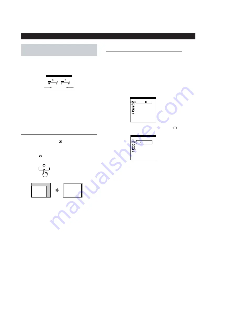
The BRIGHTNESS/CONTRAST OSD appears.

Automatic Sizing and
Centering of the Picture

You can easily adjust the size and centering of the picture so it
fills the screen by pressing the 

 button.

1

Turn on the monitor and computer.

2

Press the 

 button.

The picture fills the screen.

Input Signal Selection

This monitor has two signal input terminals (HD15 and
5 BNC) and can be connected to two computers. When the
power of both computers is on, manually select the input signal
you want to view as follows.

1

Turn on the monitor and both computers.

2

Press the MENU button to display the MENU OSD.

3

Highlight the OPTION OSD using the BRIGHTNESS and

CONTRAST buttons and press the MENU button again.

ON

MANUAL  DEGAUSS

UNLOCK

1 MIN

OPTION

ZZ...

1

ZZ...

INPUT

1 MIN

OPTION

UNLOCK

2

Horizontal
frequency

Vertical
frequency

2

To adjust the brightness

Press the  

¨

 (BRIGHTNESS) 

.

/

>

 buttons.

To adjust the contrast

Press the 

>

 (CONTRAST) 

?

/

/

 buttons.

Notes

This function is intended for use with a computer running

Windows or similar graphic user interface software that

provides a full-screen picture.  It may not work properly if the

background color is dark or if the input picture does not fill the

screen to the edges (such as an MS-DOS prompt).

The screen may go blank for a few seconds while performing the

Sizing and Centering function. This is not a malfunction.

Although a picture with an aspect ratio of 5:4 (resolution: 1280 

×

1024) does not fill the screen to the edges, the picture is

accurately displayed.

4

Press the 

¨

 (BRIGHTNESS) 

.

/

>

 buttons to select

(INPUT).

5

Press the 

>

 (CONTRAST) 

?

/

/

 buttons to select

“1” or “2.”

When you select “1”

The monitor displays the signal from the computer

connected to the HD15 terminal.

When you select “2”

The monitor displays the signal from the computer

connected to the 5 BNC terminals.

When you connect computers to both terminals

If you restart the computer you are viewing, or that computer
goes into power saving mode, the monitor may automatically
switch to the signal from the other computer. This is because
the monitor automatically switches from an interrupted signal
to a constant signal. If this happens, manually select the
computer signal you want to view.

BRIGHTNESS/CONTRAST

26

26

80.0kHz/   75Hz

Содержание D1626HT - UltraScan 1600HS - 21" CRT Display

Страница 1: ...4 3 8 11 1 2 in Input signal Video Analog RGB 75 Ω typical 0 7 Vp p Positive Sync External HD VD Composite Polarity Free TTL Video Composite Sync on green 0 3 Vp p Negative Deflection frequency Horizontal 30 to 107 kHz Vertical 48 to 160 Hz AC input voltage current 100 to 240 V 50 60 Hz 2 0 1 0 A Inrush current 120 VAC 50 A 240 VAC 80 A Power consumption Maximum 160 W Nominal 120 W 409 BTU h Dimen...

Страница 2: ...UNE PIÈCE PORTANT LE NUMÉRO SPECIFIÉ LES RÉGLAGES DE CIRCUIT DONT L IMPORTANCE EST CRITIQUE POUR LA SÉCURITÉ DU FONCTIONNEMENT SONT IDENTIFIÉS DANS LE PRÉSENT MANUEL SUIVRE CES PROCÉDURES LORS DE CHAQUE REMPLACEMENT DE COMPOSANTS CRITIQUES OU LORSQU UN MAUVAIS FONCTIONNE MENT EST SUSPECTÉ After correcting the original service problem perform the fol lowing safety checks before releasing the set to...

Страница 3: ...nsumption as follows Power consumption 160 W 100 W 15 W 5 W 0 W Recovery time Approx 3 sec Approx 3 sec Approx 10 sec u indicator Green Green and orange alternate Green and orange alternate Orange Off Orange flashing Power consumption mode Normal operation Standby 1st mode Suspend 2nd mode Active off 3rd mode Power off Failure mode 1 2 3 4 5 6 Failre B failure Horizontal Vertical Deflection failur...

Страница 4: ... Removal 13 2 3 G Board Removal 14 2 4 A Board Removal 14 2 5 L Board Removal 15 2 6 I O TERMINAL Board Removal 15 2 7 Service Position 16 2 8 H and J Boards Removal 16 2 9 Picture Tube Removal 17 3 SAFETY RELATED ADJUSTMENT 18 4 ADJUSTMENTS 19 5 DIAGRAMS 5 1 Block Diagrams 21 5 2 Frame Shcematic Diagram 27 5 3 Circuit Boards Location 29 5 4 Schematic Diagrams and Printed Wiring Boards 29 1 Schema...

Страница 5: ...rts and Controls Rear 1 RESET button pages 7 and 11 Resets the adjustments to the factory settings 2 AUTO SIZING AND CENTERING button page 6 Automatically adjusts the size and centering of the images 3 BRIGHTNESS buttons page 6 Adjust the picture brightness Operate as the buttons when adjusting other items 4 MENU button page 7 Displays the MENU OSD 5 CONTRAST buttons page 6 Adjust the contrast Ope...

Страница 6: ...is intended for use with a computer running Windows or similar graphic user interface software that provides a full screen picture It may not work properly if the background color is dark or if the input picture does not fill the screen to the edges such as an MS DOS prompt The screen may go blank for a few seconds while performing the Sizing and Centering function This is not a malfunction Althou...

Страница 7: ... Adjust the monitor setting using the BRIGHTNESS and CONTRAST buttons To reset the current item to its original setting press the RESET button while the item s adjustment OSD is displayed 5 When you finish adjusting the setting press the MENU button to return to the MENU OSD Press the MENU button twice to return to normal viewing Resetting If you press the RESET button while an OSD is displayed on...

Страница 8: ...ire cancellation CANCEL MOIRE must be ON for MOIRE ADJUST to appear on the screen Adjusting the Settings 1 Using the COLOR OSD You can adjust the monitor s color temperature using the COLOR OSD For example you can adjust the monitor to match the colors of a printed picture You can adjust the color temperature from 9300K blue white to 5000K warm red This setting is stored in memory for all input si...

Страница 9: ...he MENU button again 3 Press the BRIGHTNESS buttons to select the desired adjustment item 4 Press the CONTRAST buttons to activate the manual degauss select the input signal move the OSD position change the Power Saving delay time or lock the user controls 5 Press the MENU button once to return to the MENU OSD or press it twice to return to normal viewing Degauss If a second degauss cycle is neede...

Страница 10: ...t the GEOMETRY OSD using the BRIGHTNESS and CONTRAST buttons and press the MENU button again 3 Press the BRIGHTNESS buttons to select the desired geometry adjustment 4 Press the CONTRAST buttons to adjust the geometry 5 Press the MENU button once to return to the MENU OSD or press it twice to return to normal viewing Select ROTATION PINCUSHION PIN BALANCE KEYSTONE KEY BALANCE To adjust the picture...

Страница 11: ...pecifications Picture tube 0 25 0 27 mm aperture grill pitch 21 inches measured diagonally 90 degree deflection Phosphor Type P22 Transmission Ratio Approx 39 Faceplate Anti Reflective AR Anti Static AS coating Viewable image size Approx 403 8 302 2 mm w h 16 12 in 19 8 viewing image Resolution Horizontal Max 1600 dots Vertical Max 1200 lines Display picture size Approx 388 291 mm w h 15 3 8 11 1 ...

Страница 12: ...pecifications Picture tube 0 25 0 27 mm aperture grill pitch 21 inches measured diagonally 90 degree deflection Phosphor Type P22 Transmission Ratio Approx 39 Faceplate Anti Reflective AR Anti Static AS coating Viewable image size Approx 403 8 302 2 mm w h 16 12 in 19 8 viewing image Resolution Horizontal Max 1600 dots Vertical Max 1200 lines Display picture size Approx 388 291 mm w h 15 3 8 11 1 ...

Страница 13: ...BVTP 3 x 10 D board Screw P 3 5 x 20 Open the D block in the direction of the arrow and remove of the arrow Three hooks 6 A B A B Screw BVTT 4 x 8 1 2 3 4 5 Top cover Four screws BVTT 4 x 8 Four screws BVTT 4 x 8 Video shield 4 5 6 8 Screw cover Cabinet 3 Four screws BVTP 4 x 16 2 1 Two claws Screw cover 7 ...

Страница 14: ...the direction of the arrow and remove of the arrow Two screws BVTT 4 x 8 Three hooks Two screws BVTP 3 x 10 G shield G board B A Two printed circuit board holders A B 1 7 Screw BVTT 4 x 8 3 2 4 5 6 2 4 A BOARD REMOVAL A board Three screws BVTT 4 x 8 1 2 ...

Страница 15: ...626HT 15 2 5 L BOARD REMOVAL L board Four printed circuit board holders 1 2 CN5001 CN5002 CN5004 CN5003 2 6 I O TERMINAL BOARD REMOVAL Three screws BVTT 3 x 8 1 I O terminal board assy 2 CN511 CN401 CN402 ...

Страница 16: ...fer to 2 3 CAUTION SHORT If the claw is hooked opening and closing the board is impossible Do not try to do it by force If the claw is hooked opening and closing the board is impossible Do not try to do it by force Four screws Tapping screw 5 CN801 H board Two screws BVWHTP 3 x 12 Bezel 1 2 3 4 Claw J board 7 CN891 Shaft Claw Claw 5 6 ...

Страница 17: ...hardly The shatter hook terminal will stick out or hurt the rubber REMOVAL OF ANODE CAP NOTE Short circuit the anode of the picture tube and the anode cap to the metal chassis CRT shield or carbon painted on the CRT after removing the anode REMOVING PROCEDURES 1 Turn up one side of the rubber cap in the direction indicated by the arrow a 2 Using a thumb pull up the rubber cap firmly in the directi...

Страница 18: ...D confirm that the Beam Current Protector Circuit works and HV go down more than 1 25 kV from the value of 1 Check Condition 1 50 mA d Beam Current Protector Circuit Check 2 1 Connect to the Constant Current Jig B between pin 1 of CN901 on D board and GND confirm that the Beam Current Protector Circuit works and TV Raster disappears Check Condition 1 59 mA e Voltage of 3rd winding of FBT 1 Confirm...

Страница 19: ...rom the non magnetic field in your estimation 4 Attach the wobbling coil to the designated part of the CRT neck 5 Attach the sensor of the landing adjustment unit on the CRT surface 6 Adjust the DY position and purity and the DY tilt and land ing of the center and 4 corners with the landing checker After adjustment set LCC SW to 13 Write terrestrial magnetism sensor reading VX and VY to LCC VX and...

Страница 20: ... fold poles magnet attached to the CRT neck upon each other Fig 1 3 Make rough adjustment of the H and V direction convergence by using 4 fold poles magnet 4 Make a rough adjustment of the V direction convergence by using V STAT Protrusions 60 Fig 1 Fig 3 Fig 2 TLV YCH YBH XBV XCV APH Set so that the protruding parts of the 2 magnet rings agree with each other Convergence Specification White Balan...

Страница 21: ...12 13 45 44 LED0 LED1 CONT VR BRT VR KEY DET ANV_DRV CN501 EEP SDA EEP SCL IC004 EEP ROM 5 6 25 26 V CLK SDA SCL IC002 ROM 47 32 33 7 5 6 CN511 C SYNC_1 V SYNC_1 C SYNC_2 V SYNC_2 DDC_SDA_1 DDC_SCL_1 DDC_SDA_2 DDC_SCL_2 CPU IC001 G CS1 VS1 CS2 VS2 F H I P70 IRQ0 DDC_SDA_2 DDC_SCL_2 KEY_DET EEP_SDA EEP_SCL LED0 LED1 P66 AN6 ASC SW OSD_SEL DAC SEL HFBP VRET DMP_CLK DMP_DO DMP_DI DMP_ID INPUT SEL 66 ...

Страница 22: ... 25 27 30 35 5 6 7 8 22 IC404 OSD R G B FBKG 17 12 3 23 14 9 1 26 28 27 26 25 24 R_IN G_IN B_IN R_OSD G_OSD B_OSD OSD_BLK CLP BLK IC402 R_DRV G_DRV B_DRV MAIN CONT OSD CONT R_OUT G_OUT B_OUT 37 42 51 18 13 4 27 25 52 DAC_SEL CLK MOSI R_IN G_IN B_IN R_OUT G_OUT B_OUT 1 CN1 KR KG KB HEATER 5 3 7 KR KG KB HEATER CN2 HEATER 15V STBY 8V CN405 CN406 L Q404 A VIDEO AMP RGB OUT BRT Q101 Q201 Q301 IC403 RG...

Страница 23: ...FASTEN ROTATION ROTATION D GND V STAT V STAT H STAT H STAT ROTATION H STA V STA ROTATION ROTATION NC HEATER NC 200V 200V GND LED2 LED3 TEMP_DRI GND GND DRIVE I SENCE VCC V SENCE AC SENCE OVP LVP GND L SENCE GND DRIVE I SENCE VCC V SENCE AC SENCE OVP LVP GND L SENCE GA POWER SW POWER SUPPLY VIDEO AMP RGB OUT DEFLECTION µ COM H USER CONTROL V STAT H STAT LCC GEO MAGNETIC SENSOR POWER SENSOR 5 3 CIRC...

Страница 24: ...D050 G 1 3 D501 B 5 3 D502 B 5 B 1 D503 F 5 3 D504 E 5 E 1 D505 D 4 D 1 D506 B 4 B 2 D507 B 4 B 2 D508 B 4 B 2 D509 E 5 E 1 D510 D 4 D 2 D511 C 3 C 3 D512 C 4 C 2 D513 F 1 3 D514 A 5 A 1 D515 E 3 3 D516 E 3 3 D518 A 4 3 D519 C 5 C 1 D520 B 4 B 2 D521 B 2 3 D660 E 2 3 D701 F 5 3 D704 F 5 3 D705 F 1 3 D706 G 5 3 D709 G 5 G 1 D713 E 1 E 5 D714 E 1 E 5 D715 E 1 E 5 D718 E 5 3 D720 E 2 E 4 D721 E 1 E 5...

Страница 25: ...P 470 CHIP 10k CHIP 22 FPRD 1 2k RN CP 1 2k RN CP 10k CHIP 220 CHIP 220 CHIP 22k RN CP 4 7k RN CP 68 10W 10 FPRD 1k CHIP 100 CHIP 0 CHIP 10k CHIP 10k CHIP 1k CHIP 2 2k CHIP 10k CHIP 1 5M CHIP 100k CHIP HDT HST DFT 4MHz 4700p 2kV PP 0 0047 PT 100V 1SS119 0 056 400V PP 1SS119 0 01 B CHIP 47p CH CHIP MA111 MA111 680k RN CP MA111 1 10 HRC 11P WHT S MICRO 5P WHT S MICRO 11P WHT S MICRO 3P WHT S MICRO 9...

Страница 26: ...5 6 2 3 4 5 6 7 8 9 10 11 12 13 14 1 2 3 4 5 1 2 3 4 C5305 R5310 R5312 D5301 D5303 C5310 R5320 C5307 C5311 R5101 R5102 C5111 R5116 R5112 R5120 D5103 D5101 C5110 C5204 R5202 R5201 R5203 R5205 R5207 R5316 C5202 C5201 C5405 R5412 C5410 R5420 D5401 R5001 C5003 C5005 R5006 R5311 R5317 R5108 R5117 R5411 R5408 R5417 R5414 R5421 R5314 R5321 R5114 R5121 R5204 R5501 R5503 R5422 R5410 R5406 R5416 R5419 C5408...

Страница 27: ...me of semiconductors in silk screen printed circuit 3 6 8 D5501 D5101 D5103 D5201 D5301 D5303 D5401 D5403 D5002 Ref Refer to Terminal name of semiconductors in silk screen printed circuit see page 29 41 42 43 l V STAT H STAT LLC GEO MAGNETIC SENSOR L BOARD Conductor Side b b b b b Pattern from the side which enables seeing b b b b b Pattern of the rear side b b b b b Pattern from the side which en...

Страница 28: ...2 2k CHIP 10k CHIP 100 CHIP 47k CHIP 10M 1W RN 2 2M 1W RN 2 2k CHIP 10k RN CP 4 7k CHIP 10k CHIP 10k CHIP 1 FPRD 1 FPRD MA111 0 1 25V B CHIP 22p CH CHIP 22p CH CHIP 100 CHIP 100 CHIP 100 CHIP 100 CHIP 100 CHIP 100 CHIP 1 5k CHIP 0 1 25V B CHIP 2SB709A G SYNC 2SC2412 G SYNC 2SB709A G SYNC 1 5k CHIP 4 7k CHIP 10 1 5k CHIP 1PS226 115 1PS226 115 47 16V 47 16V 47 16V 1SS226 TE85L 1SS226 TE85L 1SS226 TE...

Страница 29: ... 1 Q409 D 3 1 Q410 D 1 D 3 DIODE D101 A 1 7 D102 A 1 7 D103 B 3 3 D104 C 1 3 D105 C 3 3 D106 B 3 3 D107 B 3 3 D201 A 1 7 D202 A 1 7 D203 B 3 3 D204 C 1 3 D205 C 3 3 D206 B 3 3 D207 B 3 3 D301 A 2 7 D302 A 1 7 D303 B 3 3 D304 C 1 3 D305 C 2 3 D306 B 2 3 D307 B 3 3 D401 B 2 3 D402 B 3 3 D404 C 3 3 D405 D 3 3 D406 D 3 3 D407 D 1 3 D408 D 1 3 D409 D 1 3 Component Side Conductor Side Component Side Con...

Страница 30: ...D1626HT D1626HT 49 50 5 4 SEMICONDUCTORS ...

Страница 31: ...CUIT BOARD 19 3 703 141 00 HOLDER PRINTED CIRCUIT BOARD 20 8 933 277 00 G BOARD COMPLETE 21 21 8 933 269 00 GA BOARD COMPLETE 22 4 061 604 31 CABINET 23 4 061 605 31 COVER SCREW 24 4 060 358 41 COVER ECS 25 4 062 515 01 LABEL INFORMATION 26 1 543 793 11 FILTER CLAMP FEPRITE CORE 27 4 061 694 02 SHEET INSULATE 1 X 4035 195 1 BEZEL ASSY 2 3 2 4 061 970 21 BUTTON POWER 3 4 042 593 01 SPRING COMPRESSI...

Страница 32: ...E DISK 15mmφ 76 4 059 493 01 PERMALLOY 90 CONV CORRECT 77 4 062 511 01 SPACER PICTURE TUBE 51 8 738 791 81 ITC ASSY 21SRG R1 52 54 72 52 8 738 791 05 PICTURE TUBE 21SRG except SH model 52 8 738 792 05 PICTURE TUBE 21SRG SH model 53 8 451 493 11 DEFLECTIN YOKE Y21SRL M 54 4 050 492 01 SPACER DY 55 4 047 316 01 SPRING TENSION 56 1 416 437 11 COIL DEMAGNETIC 57 1 416 140 12 COIL LANDING CORRECTION 58...

Страница 33: ...61 809 01 CUSHION UPPER ASSY 102 4 041 927 31 BAG POLYETHYLENE 103 4 061 810 01 CUSHION LOWER ASSY 104 4 062 893 01 INDIVIDUAL CARTON 105 3 862 000 11 MANUAL INSTRUCTION 106 1 769 752 11 CORD SET POWER 7A 125V J model 106 1 776 027 51 CORD SET POWER 10A 125V U C model 107 1 177 743 11 CABLE ASSY 15P D SUB X2 CONNECTOR 101 102 103 104 105 106 107 The components identified by shading and mark are cr...

Страница 34: ... CERAMIC CHIP 0 01MF 10 50V C204 1 104 664 11 ELECT 47MF 20 25V C205 1 164 232 11 CERAMIC CHIP 0 01MF 10 50V C206 1 164 232 11 CERAMIC CHIP 0 01MF 10 50V C207 1 164 004 11 CERAMIC CHIP 0 1MF 10 25V C208 1 107 903 11 ELECT 2 2MF 20 50V C209 1 163 243 11 CERAMIC CHIP 47PF 5 50V C210 1 163 275 11 CERAMIC CHIP 0 001MF 5 50V C211 1 163 017 00 CERAMIC CHIP 0 0047MF 10 50V C212 1 164 004 11 CERAMIC CHIP ...

Страница 35: ...1 ELECT 47MF 20 25V C489 1 164 004 11 CERAMIC CHIP 0 1MF 10 25V CONNECTOR CN401 1 564 521 11 PLUG CONNECTOR 6P CN402 1 564 522 11 PLUG CONNECTOR 7P CN403 1 564 523 11 PLUG CONNECTOR 8P CN405 1 564 524 11 PLUG CONNECTOR 9P CN406 1 766 179 11 PIN CONNECTOR PC BOARD 2P CN407 1 564 522 11 PLUG CONNECTOR 7P DIODE D101 8 719 062 51 DIODE 1PS226 115 D102 8 719 062 51 DIODE 1PS226 115 D103 8 719 404 49 DI...

Страница 36: ... 1 216 027 00 RES CHIP 120 R124 1 219 497 11 CARBON 22 5 1 2W R125 1 216 693 11 METAL CHIP 56K 0 50 1 10W R126 1 216 097 91 RES CHIP 100K R127 1 216 035 00 RES CHIP 270 R128 1 216 121 91 RES CHIP 1 0M R129 1 218 776 11 METAL CHIP 1M 0 50 1 10W R130 1 216 097 91 RES CHIP 100K R131 1 216 057 00 RES CHIP 2 2K R132 1 216 035 00 RES CHIP 270 R133 1 216 049 91 RES CHIP 1 0K R134 1 216 097 91 RES CHIP 10...

Страница 37: ... CHIP 1 0K R410 1 216 049 91 RES CHIP 1 0K R411 1 216 065 00 RES CHIP 4 7K R412 1 216 053 00 RES CHIP 1 5K R413 1 216 065 00 RES CHIP 4 7K R415 1 216 065 00 RES CHIP 4 7K R416 1 216 049 91 RES CHIP 1 0K R417 1 216 089 91 RES CHIP 47K R418 1 260 127 11 CARBON 220K 5 1 2W R419 1 216 687 11 METAL CHIP 33K 0 50 1 10W R420 1 216 691 11 METAL CHIP 47K 0 50 1 10W R421 1 216 103 00 RES CHIP 180K R422 1 21...

Страница 38: ...S CHIP 47K R7513 1 216 093 00 RES CHIP 68K 8 933 277 00 G BOARD COMPLETE 4 382 854 11 SCREW M3X10 P SW Q610 Q640 D610 D611 D672 7 322 065 72 RUBBER RTV SE 9168 130G R640 C671 CAPACITOR C601 1 113 900 51 CERAMIC 470PF 10 250V C602 1 113 900 51 CERAMIC 470PF 10 250V C603 1 107 533 51 FILM 1MF 20 250V C604 1 107 533 51 FILM 1MF 20 250V C605 1 113 926 91 CERAMIC 0 0047MF 250V C606 1 113 926 91 CERAMIC...

Страница 39: ...1 19 DIODE 1SS119 25 D693 8 719 404 49 DIODE MA111 FUSE F601 1 576 233 11 FUSE H B C 6 3A 250V 1 533 223 11 HOLDER FUSE F601 FERRITE BEAD FB610 1 410 396 41 INDUCTOR 0 45UH FB611 1 410 396 41 INDUCTOR 0 45UH FB612 1 410 396 41 INDUCTOR 0 45UH IC IC630 8 749 013 03 IC DM 60 IC660 8 759 470 64 IC TOP223Y BB IC690 8 749 011 42 IC SI 3050F IC691 8 759 140 85 IC UPC1093J COIL L610 1 416 409 11 COIL CHO...

Страница 40: ... 470K R672 1 216 049 91 RES CHIP 1 0K R673 1 249 413 11 CARBON 470 5 1 4W F R674 1 249 377 11 CARBON 0 47 5 1 4W F R675 1 260 292 11 CARBON 1 5 1 2W R676 1 249 413 11 CARBON 470 5 1 4W R680 1 216 073 00 RES CHIP 10K R681 1 216 049 91 RES CHIP 1 0K R682 1 216 065 00 RES CHIP 4 7K R683 1 216 025 91 RES CHIP 100 R685 1 216 073 00 RES CHIP 10K R686 1 216 049 91 RES CHIP 1 0K R687 1 216 049 91 RES CHIP...

Страница 41: ...50V C059 1 164 232 11 CERAMIC CHIP 0 01MF 10 50V C060 1 126 964 11 ELECT 10MF 20 50V C061 1 164 232 11 CERAMIC CHIP 0 01MF 10 50V C062 1 164 004 11 CERAMIC CHIP 0 1MF 10 25V C063 1 137 399 11 FILM 0 1MF 5 50V C065 1 126 965 11 ELECT 22MF 20 50V C066 1 164 232 11 CERAMIC CHIP 0 01MF 10 50V C067 1 163 243 11 CERAMIC CHIP 47PF 5 50V C068 1 126 964 11 ELECT 10MF 20 50V C069 1 164 232 11 CERAMIC CHIP 0...

Страница 42: ...2 11 CERAMIC CHIP 0 01MF 10 50V C750 1 126 964 11 ELECT 10MF 20 50V C751 1 164 232 11 CERAMIC CHIP 0 01MF 10 50V C901 1 107 889 11 ELECT 220MF 20 25V C902 1 163 809 11 CERAMIC CHIP 0 047MF 10 25V C903 1 163 259 91 CERAMIC CHIP 220PF 5 50V C904 1 137 605 11 FILM 0 01MF 10 250V C905 1 104 653 11 ELECT 220MF 20 16V C906 1 106 220 00 MYLAR 0 1MF 10 100V C907 1 119 748 11 ELECT 33MF 20 400V C908 1 136 ...

Страница 43: ... 719 911 19 DIODE 1SS119 25 D718 8 719 976 99 ZENER DIODE DTZ5 1B D720 8 719 028 72 DIODE RGP02 17EL 6433 D721 8 719 028 72 DIODE RGP02 17EL 6433 D901 8 719 404 49 DIODE MA111 D902 8 719 404 49 DIODE MA111 D903 8 719 911 19 DIODE 1SS119 25 D904 8 719 404 49 DIODE MA111 D905 8 719 404 49 DIODE MA111 D906 8 719 404 49 DIODE MA111 D907 8 719 158 49 ZENER DIODE RD12SB2 D908 8 719 158 49 ZENER DIODE RD...

Страница 44: ...098 01MR Q525 8 729 042 43 TRANSISTOR 2SK2098 01MR Q526 8 729 042 43 TRANSISTOR 2SK2098 01MR Q527 8 729 042 43 TRANSISTOR 2SK2098 01MR Q528 8 729 042 43 TRANSISTOR 2SK2098 01MR Q660 8 729 033 26 TRANSISTOR DTA114GKAT146 Q661 8 729 033 25 TRANSISTOR DTC114GKA Q701 8 729 800 32 TRANSISTOR 2SC2362K G Q703 8 729 178 43 TRANSISTOR 2SC2784 E Q704 8 729 207 82 TRANSISTOR 2SC3421 Y Q705 8 729 204 91 TRANS...

Страница 45: ...627 11 METAL CHIP 100 0 50 1 10W R513 1 215 860 11 METAL OXIDE 33 5 1W F R514 1 211 796 11 FUSIBLE 1 5 1 2W F R515 1 216 675 11 METAL CHIP 10K 0 50 1 10W R516 1 247 815 91 CARBON 220 5 1 4W R517 1 216 065 00 RES CHIP 4 7K R518 1 216 097 91 RES CHIP 100K R519 1 216 393 00 METAL OXIDE 2 2 5 3W F R520 1 216 393 00 METAL OXIDE 2 2 5 3W F R521 1 249 413 11 CARBON 470 5 1 4W F R522 1 216 423 11 METAL OX...

Страница 46: ... CHIP 10K R732 1 216 073 00 RES CHIP 10K R733 1 219 746 11 CARBON 1K 5 1 2W R734 1 215 881 11 METAL OXIDE 15 5 2W F R737 1 249 377 11 CARBON 0 47 5 1 4W F R738 1 249 377 11 CARBON 0 47 5 1 4W F R739 1 249 413 11 CARBON 470 5 1 4W F R741 1 249 430 11 CARBON 12K 5 1 4W R742 1 249 419 11 CARBON 1 5K 5 1 4W R743 1 216 049 91 RES CHIP 1 0K R748 1 216 683 11 METAL CHIP 22K 0 50 1 10W R749 1 216 025 91 R...

Страница 47: ...99 21 GAP SPARK TRANSFORMER T501 1 429 303 21 TRANSFORMER FERRITE HDT T502 1 416 401 11 COIL CHOKE 5MMH T503 1 431 413 11 TRANSFORMER FERRITE HST T504 1 416 257 11 COIL CHOKE HCC 2 0MH T701 1 431 414 11 TRANSFORMER FERRITE DFT T901 1 416 402 11 COIL CHOKE 500UH T902 X 4035 170 1 TRANSFORMER ASSY FLYBACK NX 4142 J1D4 THERMISTOR TH501 1 807 796 11 THERMISTOR TH502 1 807 796 11 THERMISTOR CRYSTAL X00...

Страница 48: ...11 CERAMIC CHIP 0 1MF 10 25V C5305 1 104 664 11 ELECT 47MF 20 25V C5306 1 164 004 11 CERAMIC CHIP 0 1MF 10 25V C5307 1 137 399 11 FILM 0 1MF 5 50V C5308 1 164 004 11 CERAMIC CHIP 0 1MF 10 25V C5309 1 164 004 11 CERAMIC CHIP 0 1MF 10 25V C5310 1 104 664 11 ELECT 47MF 20 25V C5311 1 137 399 11 FILM 0 1MF 5 50V C5401 1 164 004 11 CERAMIC CHIP 0 1MF 10 25V C5403 1 164 232 11 CERAMIC CHIP 0 01MF 10 50V...

Страница 49: ...0K 5 1 4W F R5315 1 215 882 00 METAL OXIDE 22 5 2W F R5316 1 216 073 00 RES CHIP 10K R5317 1 216 308 00 RES CHIP 4 7 R5319 1 216 073 00 RES CHIP 10K R5320 1 249 383 11 CARBON 1 5 5 1 4W F R5321 1 249 441 11 CARBON 100K 5 1 4W F R5322 1 215 882 00 METAL OXIDE 22 5 2W F R5401 1 249 383 11 CARBON 1 5 5 1 4W F R5402 1 249 383 11 CARBON 1 5 5 1 4W F R5406 1 216 689 11 RES CHIP 39K R5407 1 216 079 00 RE...

Страница 50: ...re critical for safety Replace only with part number specified Les composants identifiés per un tramé et une marque sont critiques pour la sécurité Ne les remplacer que par une piéce portant le numéro spécifié 70 Sony Corporation Display Company Computer Display Dept 9 978 601 01 English 97KL05017 1 Printed in Japan 1997 11 ...

Отзывы: