background image

Installing MC

Align the MC with the bay. Make sure the connector is positioned correctly before inserting into the bay.

Insert the MC in the bay and slide it in until it is flush with the bay.

Installation and Service Manual

Installing and removing system components

125

Содержание B11S Series

Страница 1: ...Dell EMC DSS 9000R Regulatory Model B11S Series Series Regulatory Type B11S001 ...

Страница 2: ... to hardware or loss of data and tells you how to avoid the problem WARNING A WARNING indicates a potential for property damage personal injury or death Copyright 2018 Dell Inc or its subsidiaries All rights reserved Dell EMC and other trademarks are trademarks of Dell Inc or its subsidiaries Other trademarks may be trademarks of their respective owners 2018 01 Rev A00 ...

Страница 3: ...d 34 Block controller BC modules 36 Fan power distribution boards FPDB 38 Fan modules 40 4 Power bay overview 41 Power bay specifications 43 Power bay unit 44 Power bay allocation 44 Rear view 46 Power supply unit PSU 48 Power bay power module PBPM 50 Management controller MC module 51 Rear IO module 53 DSS 9000 rack manager module 55 5 Bus bar overview 57 Rack level bus bar 57 Bus bar top 57 Bus ...

Страница 4: ...e 96 Installing fan module 98 Fan blocks 100 Removing fan block 100 Installing fan block 102 Fan power distribution boards FPDB 104 Removing FPDB 105 Installing FPDB 107 Block Controller Distribution Board BCDB 111 Removing BCDB 111 Installing BCDB 117 Block controllers BC 119 Removing BC 119 Installing BC 121 Management controllers MC 123 Removing MC 123 Installing MC 125 Rack manager board RMB a...

Страница 5: ...Removing PIB 137 Installing PIB 147 7 Troubleshooting list 158 8 Getting help 160 Contacting Dell 160 Documentation feedback 160 Installation and Service Manual Contents 5 ...

Страница 6: ... top bus bars can be assembled For more information about bus bars see Bus bar top 3 Rear cabinet The rear cabinet houses twelve system fans one block controller distribution board BCDB one block controller BC one fan cage one fan power distribution board FPDB and one rear cabinet base 4 Bus bar middle Bridge bus bar located between top and bottom bus bars For more information about bus bars see B...

Страница 7: ...optional Reversible front door can be configured to open from left or right with lock Rack specifications Table 2 Rack specifications Item Description Height Available rack options 29U 1 466 4 mm 57 73 inch 42U 1 970 4 mm 77 57 inch 44U 2 071 2 mm 81 54 inch 48U 2 272 8 mm 89 48 inch 50U 2 373 6 mm 93 45 inch Width 600 mm 23 62 inch Depth 1 200 mm 47 24 inch Net weight 29U 162 4 kg 358 lb 42U 201 ...

Страница 8: ...Power supply unit PSU blanks optional Side panels optional Shipping brackets PDU brackets Power bay protectors Bus bar protectors Rack blank fillers IM blank fillers Locating Service Tag of your system Server blanks The following lists the available server blanks for the DSS 9000 full width half width and one third width blank chassis 2 8 Installation and Service Manual Rack accessories overview ...

Страница 9: ...Figure 2 Full width server blank Installation and Service Manual Rack accessories overview 9 ...

Страница 10: ...Table 3 Full width server blank features Item Description Dimensions W x L x H 527 mm x 930 mm x 47 mm 20 75 inch x 36 61 inch x 1 85 inch 10 Installation and Service Manual Rack accessories overview ...

Страница 11: ...Figure 3 Half width server blank Installation and Service Manual Rack accessories overview 11 ...

Страница 12: ...Table 4 Full width server blank features Item Description Dimensions W x L x H 262 2 mm x 930 mm x 47 mm 10 32 inch x 36 61 inch x 1 85 inch 12 Installation and Service Manual Rack accessories overview ...

Страница 13: ...Figure 4 One third width server blank Installation and Service Manual Rack accessories overview 13 ...

Страница 14: ...ank features Item Description Dimensions W x L x H 174 3 mm x 930 mm x 47 mm 6 86 inch x 36 61 inch x 1 85 inch Power supply unit PSU blanks optional Figure 5 PSU blank 14 Installation and Service Manual Rack accessories overview ...

Страница 15: ...Side panels optional Figure 6 Filler panel Installation and Service Manual Rack accessories overview 15 ...

Страница 16: ...Shipping brackets Figure 7 Shipping bracket 16 Installation and Service Manual Rack accessories overview ...

Страница 17: ...Figure 8 Shipping bracket Installation and Service Manual Rack accessories overview 17 ...

Страница 18: ...PDU brackets 18 Installation and Service Manual Rack accessories overview ...

Страница 19: ...Figure 9 PDU bracket Installation and Service Manual Rack accessories overview 19 ...

Страница 20: ...Power bay protectors Figure 10 Power bay protector 20 Installation and Service Manual Rack accessories overview ...

Страница 21: ...Bus bar protectors Figure 11 0 5GU bus bar protector Installation and Service Manual Rack accessories overview 21 ...

Страница 22: ...Figure 12 1GU bus bar protector 22 Installation and Service Manual Rack accessories overview ...

Страница 23: ...Rack blank fillers Figure 13 1GU rack blank fillers Installation and Service Manual Rack accessories overview 23 ...

Страница 24: ...Figure 14 2GU rack blank fillers 24 Installation and Service Manual Rack accessories overview ...

Страница 25: ...Figure 15 3GU rack blank fillers Installation and Service Manual Rack accessories overview 25 ...

Страница 26: ...Figure 16 5GU rack blank fillers 26 Installation and Service Manual Rack accessories overview ...

Страница 27: ...IM blank fillers Figure 17 IM blank fillers Installation and Service Manual Rack accessories overview 27 ...

Страница 28: ...y a unique Express Service Code and Service Tag number The information is on a sticker on the right front of the system This information is used by Dell to route support calls to the appropriate personnel 28 Installation and Service Manual Rack accessories overview ...

Страница 29: ...Service Tag BMMYG92 Service Tag BMMYG92 Service Tag BMMYG92 Figure 18 Service Tag location Installation and Service Manual Rack accessories overview 29 ...

Страница 30: ...Rear cabinet overview 3 30 Installation and Service Manual Rear cabinet overview ...

Страница 31: ...us 1 x ID 4 x fan fail Switch Reset switch local 4 Fan cage Supports up to twelve fan modules Width 480 mm 18 89 inch Length 114 5 mm 4 50 inch Height 116 0 mm 4 56 inch 5 Fan modules Fan module includes twelve fans 6 FPDB Fan Power Distribution Board 1 x 2x13 connector 1 x 2x10 connector 12 x 2x4 connectors 7 Rear cabinet base Supports up to twelve fan modules Topics Rear cabinet specifications B...

Страница 32: ...Rear cabinet specifications Figure 20 Rear cabinet 32 Installation and Service Manual Rear cabinet overview ...

Страница 33: ...scription Rear cabinet Includes fan modules fan cage FPDB BC BCDB and power strip brackets Dimensions W x L x H 480 mm x 114 5 mm x 167 mm 18 9 inch x 4 51 inch x 6 57 inch Installation and Service Manual Rear cabinet overview 33 ...

Страница 34: ...Block control distribution board Figure 21 Block control distribution board 34 Installation and Service Manual Rear cabinet overview ...

Страница 35: ...nnector 1 x RJ45 4 x NPIO connector 1 x HTPB connector 1 x BC connector 1 x BCM UART connector Net weight 78 6 g 2 77 ounce Operating voltage current 12 V current 0 2 A LED definition Table 9 LED LED Color Status Description LED Left Amber Solid Link speed 100Mb Off Disconnected LED Right Green Blinking LAN access Installation and Service Manual Rear cabinet overview 35 ...

Страница 36: ...Block controller BC modules Figure 22 BC module 36 Installation and Service Manual Rear cabinet overview ...

Страница 37: ...current 3 3 V current 1 A LED definition Table 11 LED definition LED Color Status Description Power Status Green On If there is no error Amber On If there is an error from anyone of these Mac address Fan image FPGA image Mosfet Ethernet link I2C FPGA configuration Blinking Infrastructure mismatch UID Blue On Off Blinking Identify BC board location Fan zone 1 2 Amber On Fan fail Off Normal work Ins...

Страница 38: ...Fan power distribution boards FPDB Figure 23 Fan power distribution board 38 Installation and Service Manual Rear cabinet overview ...

Страница 39: ...ption Board length 433 mm 17 05 inch Board width 38 mm 1 5 inch Connector 1x 2x10 connector 1x 2x13 connector 12 x 2x4 connector Net weight 129 2 g 4 56 ounce Operating voltage current 12 V current 32 A Installation and Service Manual Rear cabinet overview 39 ...

Страница 40: ...Fan modules 40 Installation and Service Manual Rear cabinet overview ...

Страница 41: ...Power bay overview 4 Installation and Service Manual Power bay overview 41 ...

Страница 42: ...connector and one 2x8 connector 5 DSS 9000 rack manager module Includes rack manager board RMB and infrastructure module IM MC and blocks of the IM are networked through a LAN 6 Power supply unit PSU Ten hot swappable power supply units 7 Management controller module Monitoring through the on board GbE to provide real time two way fan speed and power status and operational event information Topics...

Страница 43: ...Power bay specifications Figure 25 Power bay Installation and Service Manual Power bay overview 43 ...

Страница 44: ...a power bay which houses up to ten AC power supply units PSUs to fully support the operational requirements of the rack enclosure Figure 26 Power bay 1 MC 10 PSU model front view Table 15 Power bay 1 MC 10 PSU model front view No Item Description 1 MC One management controller module 2 Power supply unit Ten hot swappable power supply unit bays Power bay allocation When populating the PSU bays make...

Страница 45: ...NOTE To meet power requirements a minimum of six power supply units must be installed Make sure to first populate power bays 1 to 6 Installation and Service Manual Power bay overview 45 ...

Страница 46: ...Rear view 46 Installation and Service Manual Power bay overview ...

Страница 47: ... be fed to or from the rear of the cabinet and prevents dust ingress 3 1U bus bar protector Cover to prevent contact with the bus bar and an electrical short circuit 4 Infrastructure module Includes RJ45 ports UID power status LEDS Reset button ICs MCU Ethernet switch SPI ROM EEPROM TMP sensor and RS232 driver receiver Installation and Service Manual Power bay overview 47 ...

Страница 48: ...Power supply unit PSU 48 Installation and Service Manual Power bay overview ...

Страница 49: ...s Table 19 PSU specifications PSU wattage Class Heat dissipation maximum Frequency Voltage Maximum input current 2000 W AC Platinum 675 37 BTU hr 50 60 Hz 100 240 V AC autoranging 11 5 A NOTE Heat dissipation is calculated using the PSU wattage rating NOTE This system is also designed to connect to the IT power systems with a phase to phase voltage not exceeding 230 V Installation and Service Manu...

Страница 50: ...Power bay power module PBPM Table 20 Power bay power module PBPM Item Description Supports multiple max 10 PSUs each up to 2000 W PSU Supports up to two management controller cartridges 50 Installation and Service Manual Power bay overview ...

Страница 51: ...Management controller MC module Installation and Service Manual Power bay overview 51 ...

Страница 52: ...ating voltage current 12 V current 1 3 A LED definition Table 22 LED LED Color Status Description LAN port Status Green On 1G LAN speed Amber On 10M 100M LAN speed Activity Green Blinking Traffic access Power Status Green On Power on Amber On Power on fail UID Blue On Off Blinking Identify MC board location Error Green On If there is no error Amber Blinking Infrastructure mismatch On Link between ...

Страница 53: ...Rear IO module Installation and Service Manual Power bay overview 53 ...

Страница 54: ...onnector 1 x 1x6 connector 1 x 2x8 connector LED definition Table 24 LED LED Color Status Description LAN1 port Status Green On 1G LAN speed Amber On 10M 100M LAN speed Activity Green Blinking Traffic access LAN1 port Status Green On 10M 100M LAN speed Amber On 1G LAN speed Activity Green Blinking Traffic access 54 Installation and Service Manual Power bay overview ...

Страница 55: ...323 25 mm 12 73 inch Board width 242 3 mm 9 54 inch Net Weight 1 050 g 37 03 ounce Connector 2 x 8 port RJ45 1 x 2 port RJ45 1 x 2x2 Power connector 1 x USB 1 x 1x5 connector 1 x Micro USB Switch 1 x Reset Button Operating voltage current 12 V current 2 A Infrastructure module LED definition Installation and Service Manual Power bay overview 55 ...

Страница 56: ...dress I2C Blinking Infrastructure mismatch or fan fault 3 UID Blue On Off Blinking Identify IM board location 4 Block 1 10 Right LED Green Blinking Active Left LED Green On Link speed 1Gb Off No link 5 PB 1 4 Right LED Green Blinking Active Left LED Yellow On Link speed 100Mb Off Link speed 10Mb or no link 6 Gb 1 4 Right LED Green Blinking Active Left LED Green On Link speed 1Gb Yellow On Link spe...

Страница 57: ...level bus bar Block level bus bar Power bay level bus bars Rack level bus bar Bus bar top The top of the rack includes two bus bars positive and negative The bus bars are coupled to the middle bus bars for upward distribution of the system s power Figure 35 Bus bar top P positive red 5 Installation and Service Manual Bus bar overview 57 ...

Страница 58: ...k Bus bar middle The middle of the rack includes two bus bars positive and negative The bus bars couple the power block and the top bus bars for upward distribution of the system s power 58 Installation and Service Manual Bus bar overview ...

Страница 59: ...Figure 37 Bus bar middle P positive red Installation and Service Manual Bus bar overview 59 ...

Страница 60: ...Figure 38 Bus bar middle N negative black 60 Installation and Service Manual Bus bar overview ...

Страница 61: ...e coupled to the middle bus bars for downward distribution of the system s power Figure 39 Bus bar bottom P positive red Figure 40 Bus bar bottom N negative black Block level bus bar The following cross bus bar types are specific for the 6GU block Installation and Service Manual Bus bar overview 61 ...

Страница 62: ...34 4 mm 13 17 inch Width 20 mm 0 79 inch Height 34 mm 1 34 inch Thickness 4 mm 0 16 inch Figure 42 One third width cross bus bar block N negative black Table 28 One third width cross bus bar block N negative black Item Description Length 334 4 mm 13 17 inch Width 20 mm 0 79 inch Height 34 mm 1 34 inch Thickness 4 mm 0 16 inch 62 Installation and Service Manual Bus bar overview ...

Страница 63: ...Half width full width cross bus bar block Installation and Service Manual Bus bar overview 63 ...

Страница 64: ...idth full width cross bus bar block P positive red Item Description Length 334 4 mm 13 17 inch Width 20 mm 0 79 inch Height 34 mm 1 34 inch Thickness 4 mm 0 16 inch 64 Installation and Service Manual Bus bar overview ...

Страница 65: ...Figure 44 Half width full width cross bus bar block N negative black Installation and Service Manual Bus bar overview 65 ...

Страница 66: ...dth full width cross bus bar block N negative black Item Description Length 334 4 mm 13 17 inch Width 20 mm 0 79 inch Height 34 mm 1 34 inch Thickness 4 mm 0 16 inch 66 Installation and Service Manual Bus bar overview ...

Страница 67: ...Power bay level bus bars Figure 45 Power bay level bus bar Installation and Service Manual Bus bar overview 67 ...

Страница 68: ...Bus bar PB 68 Installation and Service Manual Bus bar overview ...

Страница 69: ...inch Height 58 8 mm 2 31 inch Thickness 8 mm 0 31 inch Figure 47 Bus bar PB N negative black Table 32 Bus bar PB N negative black Item Description Length 507 7 mm 19 99 inch Width 40 mm 1 57 inch Height 58 8 mm 2 31 inch Thickness 8 mm 0 31 inch Installation and Service Manual Bus bar overview 69 ...

Страница 70: ... due to servicing that is not authorized is not covered by warranty Read and follow the safety instructions that are shipped with your product System components and electronic circuit boards can be damaged by discharges of static electricity Working on systems that are still connected to a power supply can be extremely dangerous To avoid injury to yourself or damage to system follow these guidelin...

Страница 71: ...DSS 9000 rack manager module Infrastructure module Rear I O BC Servers Removing one third width server Prerequisite 1 Ensure that you read the Safety instructions Steps 1 Press the release latches on the side of the server 2 Slide the server out of the block Installation and Service Manual Installing and removing system components 71 ...

Страница 72: ...Figure 48 Removing the one third width server 72 Installation and Service Manual Installing and removing system components ...

Страница 73: ...server with the bay and insert the server into the block 2 Slide the server in until it is fully seated in the block The server locks in place after it is properly seated Installation and Service Manual Installing and removing system components 73 ...

Страница 74: ...Figure 49 Installing the one third width server 74 Installation and Service Manual Installing and removing system components ...

Страница 75: ...erequisite 1 Ensure that you read the Safety instructions Steps 1 Press the release latches on the side of the server 2 Slide the server out of the block Installation and Service Manual Installing and removing system components 75 ...

Страница 76: ...Figure 50 Removing the half width server 76 Installation and Service Manual Installing and removing system components ...

Страница 77: ...rver with the bay and insert the server into the block 2 Slide the server in until it is fully seated in the block The server locks in place after it is properly seated Installation and Service Manual Installing and removing system components 77 ...

Страница 78: ...Figure 51 Installing the half width server 78 Installation and Service Manual Installing and removing system components ...

Страница 79: ... release latches on the side of the server 2 Slide the server out of the block Figure 52 Removing full width server Installing full width server 1 Align the server with the bay and insert the server into the block 2 Slide the server in until it is fully seated in the block The server locks in place after it is properly seated Installation and Service Manual Installing and removing system component...

Страница 80: ...Figure 53 Installing the full width server 80 Installation and Service Manual Installing and removing system components ...

Страница 81: ...Ensure that you read the Safety instructions Steps 1 Grasp the tray handle with one hand and use your thumb to push the plunger up to release the HDD tray 2 Continue to hold the plunger and use the tray handle to pull the tray out from the chassis Installation and Service Manual Installing and removing system components 81 ...

Страница 82: ...Figure 54 Releasing the HDD tray 82 Installation and Service Manual Installing and removing system components ...

Страница 83: ...ay from the server Figure 55 Removing the HDD tray 4 Remove all HDDs in the HDD tray 5 Remove the screw and loosen the captive screw on the CMA Installation and Service Manual Installing and removing system components 83 ...

Страница 84: ...Figure 56 Unfastening the CMA 84 Installation and Service Manual Installing and removing system components ...

Страница 85: ...into the server bay until the HDD tray clears the plunger Figure 58 Installing the HDD tray 2 Align the CMA in the server making sure the screw wells on the CMA and server are aligned 3 Insert a screw in the CMA and tighten it to secure it to the server 4 Tighten the captive screw on the CMA Installation and Service Manual Installing and removing system components 85 ...

Страница 86: ...Figure 59 Securing the HDD tray and CMA 86 Installation and Service Manual Installing and removing system components ...

Страница 87: ...bs inch 6 32 screw 1 8 0 5 5 Install the HDDs on the HDD tray 6 Push the HDD tray in until it is fully seated in the chassis The HDD tray locks in place after it is properly seated Installation and Service Manual Installing and removing system components 87 ...

Страница 88: ...Figure 60 Installing the HDD tray 88 Installation and Service Manual Installing and removing system components ...

Страница 89: ...7 Install the full width server For more details see Installing full width server Installation and Service Manual Installing and removing system components 89 ...

Страница 90: ...Power supply units PSU 90 Installation and Service Manual Installing and removing system components ...

Страница 91: ... Prerequisite 1 Ensure that you read the Safety instructions Steps 1 Press down the PSU release latch 2 Remove the PSU from the power bay Installation and Service Manual Installing and removing system components 91 ...

Страница 92: ...Figure 61 Removing the PSU 92 Installation and Service Manual Installing and removing system components ...

Страница 93: ...are positioned correctly before sliding the PSU into the bay 2 Insert the PSU in the power bay and push it in until it is properly seated The PSU is secured when the release latch locks in place Installation and Service Manual Installing and removing system components 93 ...

Страница 94: ...Figure 62 Installing the PSU 94 Installation and Service Manual Installing and removing system components ...

Страница 95: ...Fan modules Installation and Service Manual Installing and removing system components 95 ...

Страница 96: ...only a single fan module at a time 1 Ensure that you read the Safety instructions Steps 1 Press up and hold the fan module release latch 2 Pull the fan module out 3 Remove the fan module from the fan cage 96 Installation and Service Manual Installing and removing system components ...

Страница 97: ...Figure 63 Removing the fan module Installation and Service Manual Installing and removing system components 97 ...

Страница 98: ...gn the fan module with the fan cage making sure the connectors are aligned 2 Insert the fan module in the fan cage The fan module locks in the fan cage 98 Installation and Service Manual Installing and removing system components ...

Страница 99: ...Figure 64 Installing the fan module Installation and Service Manual Installing and removing system components 99 ...

Страница 100: ... Removing fan block Prerequisite 1 Ensure that you read the Safety instructions Steps 1 Loosen the thumb screws 2 Remove the fan block 100 Installation and Service Manual Installing and removing system components ...

Страница 101: ...Figure 65 Removing the fan block Installation and Service Manual Installing and removing system components 101 ...

Страница 102: ... with the FPDB 2 Insert the fan block in the FPDB until the until slots are completely inserted into the connectors 3 Tighten the thumb screws to secure the fan block 102 Installation and Service Manual Installing and removing system components ...

Страница 103: ...Figure 66 Installing the fan block Installation and Service Manual Installing and removing system components 103 ...

Страница 104: ...Fan power distribution boards FPDB Figure 67 Fan power distribution board 104 Installation and Service Manual Installing and removing system components ...

Страница 105: ...x13 connector 12 x 2x4 connector Net weight 129 2 g 4 56 ounce Operating voltage current 12 V current 32 A Removing FPDB Prerequisites 1 Ensure that you read the Safety instructions 2 Remove the fan block Steps 1 Disconnect the cables from the cable clip 2 Disconnect the cables Installation and Service Manual Installing and removing system components 105 ...

Страница 106: ...Figure 68 Disconnecting the FPDB cables 106 Installation and Service Manual Installing and removing system components ...

Страница 107: ...ollowing figure 2 Secure the FPDB with screws Figure 70 Installing the FPDB Table 35 Assembly material Description Quantity Torque lbs inch A 6 32_STEP 2 8 0 5 B 6 32_4 5_SCREW 2 8 0 5 3 Align the hooks on the FPDB assembly with the slots on the rear cabinet base 4 Slide the FPDB assembly to install 5 Secure the FPDB assembly with screws Installation and Service Manual Installing and removing syst...

Страница 108: ...Figure 71 Installing the FPDB assembly 108 Installation and Service Manual Installing and removing system components ...

Страница 109: ...ption A bracket hooks B Fan board to bus bar screws through copper standoffs 6 Connect the cabling 7 Secure the cabling with cable clip Installation and Service Manual Installing and removing system components 109 ...

Страница 110: ...Figure 72 Securing a cable with a cable clip 110 Installation and Service Manual Installing and removing system components ...

Страница 111: ...s 1 Ensure that you read the Safety instructions 2 Remove block controller BC 3 Remove the fan block Steps 1 Disconnect the cables from the BCDB Do not disconnect the HTPB cable at this time Installation and Service Manual Installing and removing system components 111 ...

Страница 112: ...Figure 73 Disconnecting cables from a BCDB 112 Installation and Service Manual Installing and removing system components ...

Страница 113: ...le connector 2 Locate the screw securing the BCDB to the rear cabinet and remove it 3 Slide the BCDB up to disengage from the posts on the rear cabinet Installation and Service Manual Installing and removing system components 113 ...

Страница 114: ...Figure 74 Disengaging the BCDB 114 Installation and Service Manual Installing and removing system components ...

Страница 115: ...event accidental damage to either component 5 Once it is clear slide the BCDB out until the HTPB cable is accessbile Do not remove the BCDB completely at this time 6 Remove the BCDB from the rear cabinet cage 7 Disconnect the HTPB cable from the BCDB Installation and Service Manual Installing and removing system components 115 ...

Страница 116: ...Figure 75 Disconnecting an HTPB cable and removing a BCDB 116 Installation and Service Manual Installing and removing system components ...

Страница 117: ...ssembly to prevent damage to either component 4 Rotate the front of the BCDB towards the rear cabinet Make sure the keyholes on the BCDB are aligned with the posts on the rear cabinet cage Figure 76 Connecting an HTPB cable and installing a BCDB A HTPB cable connector 5 Once the BCDB is seated in the rear cabinet cage slide it down to engage the posts through the keyholes All three posts are must ...

Страница 118: ...Figure 77 Engaging the BCDB in the rear cabinet cage 7 Connect the cables to the connectors on the BCDB 118 Installation and Service Manual Installing and removing system components ...

Страница 119: ...lock controllers BC Removing BC Prerequisite 1 Ensure that you read the Safety instructions Steps 1 Loosen the captive screws on the BC 2 Remove the BC from the cage Installation and Service Manual Installing and removing system components 119 ...

Страница 120: ...Figure 79 Removing the BC 120 Installation and Service Manual Installing and removing system components ...

Страница 121: ...BC with the bay in the cage 2 Slide the BC into the rear cabinet until it is flush with the cage 3 Tighten the captive screws to secure the module to the rear cabinet Installation and Service Manual Installing and removing system components 121 ...

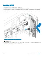
Страница 122: ...Figure 80 Installing the BC 122 Installation and Service Manual Installing and removing system components ...

Страница 123: ...Removing MC Prerequisite 1 Ensure that you read the Safety instructions Steps 1 Press down on the MC release latch 2 Remove the MC from the power bay Installation and Service Manual Installing and removing system components 123 ...

Страница 124: ...Figure 81 Removing the MC 124 Installation and Service Manual Installing and removing system components ...

Страница 125: ...he bay Make sure the connector is positioned correctly before inserting into the bay 2 Insert the MC in the bay and slide it in until it is flush with the bay Installation and Service Manual Installing and removing system components 125 ...

Страница 126: ...Figure 82 Installing the MC 126 Installation and Service Manual Installing and removing system components ...

Страница 127: ...e Prerequisite 1 Ensure that you read the Safety instructions Steps 1 Loosen the captive screws securing the rack manager module to the power bay 2 Grasp the rack manager module and slide it out of the power bay Installation and Service Manual Installing and removing system components 127 ...

Страница 128: ...Figure 83 Removing the DSS 9000 rack manager module 128 Installation and Service Manual Installing and removing system components ...

Страница 129: ...er module with the power bay 2 Slide the rack manager module into the bay until it is flush in the power bay 3 Turn the captive screws to secure the rack manager module to the power bay Installation and Service Manual Installing and removing system components 129 ...

Страница 130: ...Figure 84 Installing the DSS 9000 rack manager module 130 Installation and Service Manual Installing and removing system components ...

Страница 131: ...rack manager module from the power bay see Removing DSS 9000 rack manager module Steps 1 Remove the screws securing the IM to the bracket 2 Hold the IM by the sides and lift it out to separate from the bracket Installation and Service Manual Installing and removing system components 131 ...

Страница 132: ...Figure 85 Separating the IM from the bracket 132 Installation and Service Manual Installing and removing system components ...

Страница 133: ... edges and align it in the bracket 2 Lower it in place and make sure the screw holes on the bracket and IM are aligned 3 Secure the IM to the bracket with the screws Installation and Service Manual Installing and removing system components 133 ...

Страница 134: ...Figure 86 Assembling the IM and bracket 134 Installation and Service Manual Installing and removing system components ...

Страница 135: ... instructions Steps 1 Remove the screws from the rear IO 2 Remove the rear IO from the power bay Figure 87 Removing the rear IO module Installing rear IO module 1 Insert the rear I O into the power bay 2 Secure the rear I O to the power bay with screws Installation and Service Manual Installing and removing system components 135 ...

Страница 136: ...Figure 88 Installing the rear IO module 136 Installation and Service Manual Installing and removing system components ...

Страница 137: ...rranty Read and follow the safety instructions that came with the product Before attempting to service any part of the Power Interface Board PIB make sure the power source and power cables are turned off and disconnected It is not necessary to remove the PIB cover The following procedure is provided as reference information only Steps 1 Make sure the system is turned off Log in to the interface Th...

Страница 138: ...1 cd DEVICEHANAGER RACK1 DEVICEHANAGER RACK1 DEVICEHANAGER RACK1 DEVICEHANAGER RACK1 DEVICEHANAGER RACK1 DEVICEHANAGER RACK1 DEVICEHANAGER RACK1 stop Figure 89 Turning off the system 138 Installation and Service Manual Installing and removing system components ...

Страница 139: ... proceeding further 5 Remove the server modules from the block chassis For more details see Servers 6 Remove the securing screws attached to the chassis ears 7 Remove the securing screws attached to the cross bus bars and main bus bars Installation and Service Manual Installing and removing system components 139 ...

Страница 140: ...Figure 90 Removing the bus bar screws 140 Installation and Service Manual Installing and removing system components ...

Страница 141: ...8 The block chassis is no longer secured to the rack cabinet Installation and Service Manual Installing and removing system components 141 ...

Страница 142: ...Figure 91 Removing the block chassis from the rack cabinet 142 Installation and Service Manual Installing and removing system components ...

Страница 143: ...te the rear of the block chassis The cross bus bar x2 and PIBs x2 are visible from the rear view 11 Remove the screws securing the cross bus bar to the chassis 12 Remove the bus bars and place them on a clean surface Installation and Service Manual Installing and removing system components 143 ...

Страница 144: ...Figure 92 Removing the cross bus bars 144 Installation and Service Manual Installing and removing system components ...

Страница 145: ...13 Remove the screws securing the PIBs to the chassis 14 Remove the PIBs and place them on a clean surface Installation and Service Manual Installing and removing system components 145 ...

Страница 146: ...Figure 93 Removing PIBs 146 Installation and Service Manual Installing and removing system components ...

Страница 147: ...empting to service any part of the Power Interface Board PIB make sure the power source and power cables are turned off and disconnected The following procedure is provided as reference information only Steps 1 Make sure the system is turned off before proceeding If the system is not turned off do the following a Log in to the interface The CLI is displayed b Change directory locations to the spec...

Страница 148: ...1 cd DEVICEHANAGER RACK1 DEVICEHANAGER RACK1 DEVICEHANAGER RACK1 DEVICEHANAGER RACK1 DEVICEHANAGER RACK1 DEVICEHANAGER RACK1 DEVICEHANAGER RACK1 stop Figure 94 Turning off the system 148 Installation and Service Manual Installing and removing system components ...

Страница 149: ...the block chassis 3 Remove the new PIBs from their packaging content and inspect for damage 4 Align the PIBs on each respective location see the following figure for further details and place them on the block chassis 5 Secure the PIBs to the chassis with the provided screws Installation and Service Manual Installing and removing system components 149 ...

Страница 150: ...Figure 95 Installing PIBs 150 Installation and Service Manual Installing and removing system components ...

Страница 151: ...bar positive red with the PIBs Make sure the holes on the cross bus bar align with the holes on the PIBs 7 Secure the cross bus bar and PIBS to the chassis with the provided screws 8 Repeat for the bottom cross bus bar negative black Installation and Service Manual Installing and removing system components 151 ...

Страница 152: ...Figure 96 Installing cross bus bars 152 Installation and Service Manual Installing and removing system components ...

Страница 153: ... 8 8 0 5 9 Align the block chassis with the rack cabinet and slide in place until the securing ears are flush with the rack posts 10 Secure the block chassis to the posts with the provided screws Installation and Service Manual Installing and removing system components 153 ...

Страница 154: ...Figure 97 Installing the block chassis on the rack cabinet 154 Installation and Service Manual Installing and removing system components ...

Страница 155: ... lbs inch M5 screw 4 18 1 11 Install the server modules on the block chassis For more details see Servers 12 Secure the cross bus bars and main bus bars with the provided screws Installation and Service Manual Installing and removing system components 155 ...

Страница 156: ...Figure 98 Securing bus bars 156 Installation and Service Manual Installing and removing system components ...

Страница 157: ...Table 40 Assembly material Description Quantity Torque lbs inch M5 screw 4 16 1 Installation and Service Manual Installing and removing system components 157 ...

Страница 158: ...ils BC will move to fan table C If 2 fan fails BC will move to fan table D and fan will rotate on 100 PWM 1 or more than 1 fans become absent from right group of 6 fans fan no 7 12 Ensure all fans insert in fan wall properly IM status LED amber 1 MAC address missed or incorrect 2 I2C communication fail 1 Set MAC address using llcDebug command if its incorrect or missed 2 Ensure there is no HW dama...

Страница 159: ...ap to iDRAC through BC and MC will display PSU Error status on MC CLI under PSU target PSU fail OCP OVP OTP G5 5 FW update fail BC IM will send fail status to MC and MC will dump the llcEvents log BC IM will not lit Amber LED Any image is wrong header checksum or update G5 image on G5 5 Call Dell help Ask if the FW is official release Some server can not boot after rack power on Reset server Insta...

Страница 160: ...tomized support a Enter your system Service Tag in the Enter your Service Tag field b Click Submit The support page that lists the various support categories is displayed 4 For general support a Select your product category b Select your product segment c Select your product The support page that lists the various support categories is displayed 5 For contact details of Dell Global Technical Suppo...

Отзывы: