background image

18

CHAPTER 2: GETTING TO KNOW  YOUR DESKTOP 

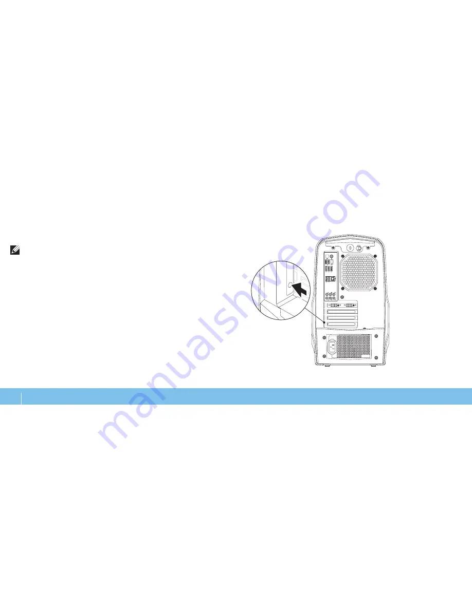
Back Light Button

Press the back light button to turn on the light to view the back panel connectors. 

This light automatically turns off after a few seconds. 

NOTE: 

In  Alienware  Aurora  Standard,  the  back  light  will  function  only 

when the computer is turned on. In Alienware Aurora ALX, the back light 

will function even when the computer is turned off, as the light is powered 

by internal batteries.

Содержание Alienware 0JYTRGA00

Страница 1: ... ALIENWARE DESKTOP MANUAL ...

Страница 2: ...n the U S and other countries Blu ray Disc is a trademark of the Blu ray Disc Association Bluetooth is a registered trademark owned by Bluetooth SIG Inc and is used by Dell Inc under license Other trademarks and trade names may be used in this manual to refer to either the entities claiming the marks and names or their products Dell Inc disclaims any proprietary interest in trademarks and trade na...

Страница 3: ...mizing Performance 27 Configuring the BIOS 28 CHAPTER 5 INSTALLING ADDITIONAL OR REPLACEMENT COMPONENTS 35 Before You Begin 36 Removing and Replacing the Side Panel 38 Inside View of Your Computer 39 Removing and Replacing Memory Module s 39 Removing and Replacing Hard Drive s 42 Removing and Replacing Expansion Card s 44 CHAPTER 6 TROUBLESHOOTING 47 Basic Hints and Tips 48 Backup and General Main...

Страница 4: ...4 ...

Страница 5: ...ew computer meets or exceeds our very demanding criteria We have tested your computer extensively in order to ensure that you enjoy the highest levels of performance In addition to a standard burn in period your computer has been evaluated using real world tools such as synthetic performance benchmarks We invite you to share your experience with your new high performance computer with us so do not...

Страница 6: ...6 ...

Страница 7: ...7 CHAPTER 1 SETTING UP YOUR DESKTOP CHAPTER 1 SETTING UP YOUR DESKTOP CHAPTER 1 SETTING UP YOUR DESKTOP ...

Страница 8: ...le connectors are not jammed between the desktop and a wall or any other object Nothing obstructs airflow in front of behind or below the desktop The desktop has enough room so that optical drives and other external storage drives can be easily accessed Before Setting Up Your Desktop Congratulations on the purchase of your Alienware Aurora Read all safety and setup instructions before connecting y...

Страница 9: ...nnector available on the graphics card on your computer NOTE A DVI or HDMI connector may be available on the graphics card you purchased You can purchase the DVI to VGA adapter HDMI to DVI adapter and additional HDMI or DVI cables at www dell com Use the appropriate cable based on the connectors available on your computer and display See the following table to identify the connectors on your compu...

Страница 10: ...10 CHAPTER 1 SETTING UP YOUR DESKTOP Connect the Network Cable Optional Connect the Keyboard and Mouse ...

Страница 11: ...ss the power button on the top of the computer Connect the Power Cable WARNING Thepowerconnectorsandpowerstripsvaryamongcountries Using an incompatible cable or improperly connecting the cable to a power strip or electrical outlet may cause fire or equipment damage ...

Страница 12: ...th the operating system settings that you selected while ordering your computer To configure the remaining settings follow the instructions on the screen NOTE For optimal performance of your computer it is recommended that you download and install the latest BIOS and drivers for your computer available at support dell com NOTE For more information on the operating system and features see support d...

Страница 13: ...rmation ready If you do not have an ISP the Connect to the Internet wizard can help you get one To set up your Internet connection Save and close any open files and exit any open programs 1 Click 2 Start Control Panel In the search box type 3 network and then click Network and Sharing Center Set up a new connection or Network Connect to the Internet The Connect to the Internet window appears NOTE ...

Страница 14: ...14 CHAPTER 1 SETTING UP YOUR DESKTOP ...

Страница 15: ...YOUR DESKTOP This chapter provides information about your new desktop to familiarize you with its various features and to get you up and running quickly CHAPTER 2 GETTING TO KNOW YOUR DESKTOP CHAPTER 2 GETTING TO KNOW YOUR DESKTOP ...

Страница 16: ...nking 2 Alienhead Lowers the drive panel when pressed The drive panel can also be lowered when the computer is turned off 3 Optical drive Plays or records CDs DVDs and Blu ray Discs 4 Optical drive bays 2 Can support additional optical drive s 5 Drive panel Covers the optical drive s or optical drive bay s NOTE The drive panel is shown in the open position 6 Optical drive eject button Ejects the o...

Страница 17: ...latch to the right to open the security lock slot and to unlock the release panel 3 Back panel connectors Connect USB audio and other devices into the appropriate connectors For more information see Back Panel Connectors on page 19 4 Expansion card slots Access connectors for any installed PCI and PCI Express cards 5 Power connector Connects to the power cable 6 Diagnostic light Indicates if the p...

Страница 18: ...w the back panel connectors This light automatically turns off after a few seconds NOTE In Alienware Aurora Standard the back light will function only when the computer is turned on In Alienware Aurora ALX the back light will function even when the computer is turned off as the light is powered by internal batteries ...

Страница 19: ...rd drives or optical drives 3 USB 2 0 connectors 6 Connect to USB devices such as a mouse keyboard printer external drive or MP3 player 4 Audio connectors Connect to speakers microphones and headphones NOTE For information on audio connectors see Connecting External Speakers on page 20 5 Network connector Connects your computer to a network or broadband device 6 IEEE 1394 connector Connects to hig...

Страница 20: ...E On computers with a sound card use the connector on the card 1 2 3 5 6 4 1 Side L R surround connector Connects to side L R surround speakers 2 Rear L R surround connector Connects to rear L R surround speakers 3 Center subwoofer connector Connects to a center speaker or subwoofer 4 Line in connector Connects to recording or playback devices such as a microphone cassette player CD player or VCR ...

Страница 21: ...21 CHAPTER 2 GETTING TO KNOW YOUR DESKTOP Top View Features Accessing the Top Panel Connectors Press the top panel downwards to access the top panel connectors 1 1 Top panel ...

Страница 22: ...E 1394 connector Connects to high speed serial multimedia devices such as digital video cameras 4 Power button Turns the computer on or off when pressed The color of the button rim indicates the power status Off the computer is either turned off in hibernate mode or is not receiving power Solid white the computer is on Blinking white the computer is in sleep or standby mode The color indicating th...

Страница 23: ...23 CHAPTER 4 USING YOUR DESKTOP CHAPTER 4 USING YOUR DESKTOP CHAPTER 4 USING YOUR DESKTOP ...

Страница 24: ... to your Alienware computer s power management controls to help increase energy efficiency Thermal Controls If you have vents present on top of your computer use thermal controls to control the thermal and venting capabilities of your computer by changing the fan speed and behavior of the vents Working With RAID A redundant array of independent disks RAID is a disk storage configuration that incre...

Страница 25: ...rd drives combine to provide 4 GB of hard drive space on which to store data NOTE In a RAID 0 configuration the size of the configuration is equal to the size of the smallest drive multiplied by the number of drives in the configuration RAID Level 1 RAID level 1 uses data mirroring to enhance data integrity When data is written to the primary drive the data is also duplicated or mirrored on the se...

Страница 26: ...ated on the primary and additional drives four 120 GB collectively have a maximum of 360 GB on which to store data A1 B1 C1 Dp A2 B2 Cp D1 A3 Bp C2 D2 Ap B3 C3 D3 RAID Level 10 A RAID 10 array combines the high data access rate of a RAID level 0 array and the data protection redundancy of a RAID level 1 mirror by striping data across two drives and mirroring that striped data on a set of two drive...

Страница 27: ...computer beyond the factory configured settings Performance Tuning Using System Setup CAUTION It is not recommended to operate the processor or other system components beyond the preset settings in the BIOS Doing so may cause system instability reduced component operating life or permanent component damage For computers with the Intel Core i7 Extreme Edition processor the BIOS has preset overclock...

Страница 28: ... NOTE Keyboardfailuremayresultwhenakeyonthekeyboardishelddown for extended periods of time To avoid possible keyboard failure press and release F2 in even intervals until the System Setup screen appears While the desktop is booting press F2 immediately before the operating 2 system logo appears to access the BIOS Setup Utility NOTE If an error occurs during POST Power On Self Test press F2 when th...

Страница 29: ...ter Memory Technology Displays the type of memory technology used Memory Speed Displays the memory speed CPU ID u Code ID Displays the processor type CPU Speed Displays the processor speed System Information Current QPI Speed Displays the QPI speed Cache L2 Displays the processor L2 cache size Cache L3 available on Aurora and Aurora ALX only Displays the processor L3 cache size Standard CMOS Featu...

Страница 30: ...he second boot device Hard Disk Drives Sets the hard drive boot priority The items displayed are dynamically updated according to the hard drives detected CD DVD Drives Sets the CD DVD drive boot priority CPU Configuration XD Bit Capability Enable XD Bit Capability to allow the processor to distinguish between the bits of code that can be executed and the ones that cannot be executed Intel Speedst...

Страница 31: ...ller s boot option SiL3132 E Sata Device available on Aurora and Aurora ALX only JMicron 362 E SATA Device available on Aurora R2 only Allows you to enable and disable the e SATA controller Integrated Devices Configure SATA 1 6 as available on Aurora and Aurora ALX only SATA Mode available on Aurora R2 only Allows you to configure the integrated hard drive controller to AHCI or RAID AHCI CD DVD Bo...

Страница 32: ...n submenu Load Level1 OC Setting Allows you to restore the Level 1 overclocking settings that were shipped from the factory only displayed with an XE processor Advance DRAM Configuration Submenu Memory Z Opens submenu to display the SPD configuration for each memory module Advanced Memory Settings Allows you to toggle to Manual mode and set all of the timing parameters tCL Displays the Column Addr...

Страница 33: ...and Uncore Voltage Adjust QPI and Uncore Voltage Advance DRAM Configuration Submenu tRRD Displays RAS to RAS delay editable in Manual Mode tRTP Displays Read to Precharge Command Delay editable in Manual Mode 1T 2T Timing Displays the Command Rate editable in Manual Mode Overclock Configuration Submenu Adjust CPU BClk MHz Allows you to adjust BClk of processor Spread Spectrum Enable Disable Spread...

Страница 34: ...ou to change the supervisor password Change User Password Allows you to change the user password You cannot use the user password to enter the BIOS setup during POST Exit Exit Options Provides options to Save Changes and Exit Discard Changes and Exit Load Optimal Defaults and Discard Changes ...

Страница 35: ...u can purchase components for your desktop at www dell com or www alienware com NOTE See the Service Manual at support dell com manuals for installation instructions of all serviceable components Parts purchased from Dell and Alienware ship with specific replacement instructions CHAPTER 5 INSTALLING ADDITIONAL OR REPLACEMENT COMPONENTS CHAPTER 5 INSTALLING ADDITIONAL OR REPLACEMENT COMPONENTS ...

Страница 36: ... order The procedures in this section may require the following tools Small flat blade screwdriver Phillips screwdriver BIOS executable update program available at support dell com Turning Off Your Desktop CAUTION To avoid losing data save and close all open files and exit all open programs before you turn off your desktop Save and close all open files and exit all open programs 1 Click 2 Start Sh...

Страница 37: ...sktop 3 Disconnect your desktop and all attached devices from their electrical 4 outlets Press the power button to ground the system board 5 Before Working Inside Your Desktop Use the following safety guidelines to help protect your desktop from potential damage and to help to ensure your own personal safety WARNING Beforeworkinginsideyourdesktop readthesafetyinformation in the SAFETY ENVIRONMENTA...

Страница 38: ... security cable slot if applicable Slide the latch to the right to unlock the release panel 2 Lift the release panel to open the side panel 3 Place the side panel in a secure location 4 NOTE Theater lighting available only on Alienware Aurora ALX turns on automatically when the side panel is removed Theater lighting is powered by internal batteries To replace the side panel push the side panel aga...

Страница 39: ...e memory module connectors on the system board see Inside 3 View of Your Computer on page 39 CAUTION The memory module s may become very hot during normal operation Allow the memory module s to cool before touching them NOTE For better access to memory module s remove the graphics card if the card is full length Spread apart the securing clips at both ends of the memory module 4 connector Lift the...

Страница 40: ... Recommended memory configuration Type Slots 1066 MHz and I333 MHz DDR3 Slots 1 and 2 or slots 1 4 To replace memory module s Aurora Aurora ALX Recommended memory configuration Type Slots 1066 MHz and I333 MHz DDR3 Slots 1 3 and 5 or slots 1 6 1600 MHz XMP Slots 1 3 and 5 ...

Страница 41: ...le into the memory module connector until the 3 memory module snaps into position If you insert the memory module correctly the securing clips snap into the cutouts at each end of the memory module NOTE If the memory module is not installed properly the computer may not boot Replace the side panel see Removing and Replacing the Side Panel on 4 page 38 Connect the power cable and all the external p...

Страница 42: ...ve cage 2 1 1 hard drive 2 release tabs 2 Removing and Replacing Hard Drive s To remove the hard drive s Follow the instructions in Before You Begin on page 1 36 Remove the side panel see Removing and Replacing the Side Panel 2 on page 38 Disconnect the power and data cable from the hard drive if applicable 3 2 1 1 power cable 2 data cable ...

Страница 43: ...ve bracket on to the new hard drive if applicable 3 Slide the new hard drive into the hard drive cage until the release tabs snap 4 into place Connect the power and data cables if applicable 5 Replace the side panel see Removing and Replacing the Side Panel on 6 page 38 Reconnect the power cable and all the external peripherals to the computer 7 Turn on the computer 8 Remove the hard drive out of ...

Страница 44: ... For a PCI Express x16 card press the securing tab on the card connector as you grasp the card by its top corners and then ease the card out of the connector 2 3 1 1 PCI Express x16 card 2 securing tab 3 connector NOTE If you are not replacing a card install a filler bracket in the empty Removing and Replacing Expansion Card s To remove a card Follow the instructions in Before You Begin on page 1 ...

Страница 45: ...e 38 Reconnect the power cable and all the external peripherals to the computer 9 Turn on the computer 10 card slot opening To replace a card Follow the instructions in Before You Begin on page 1 36 Remove the filler bracket to create a card slot opening if applicable 2 Align the card with the slot on the connector 3 Place the card in the connector and press down firmly Ensure that the card 4 is f...

Страница 46: ...46 CHAPTER 5 INSTALLING ADDITIONAL OR REPLACEMENT COMPONENTS ...

Страница 47: ...47 CHAPTER 6 TROUBLESHOOTING CHAPTER 6 TROUBLESHOOTING CHAPTER 6 TROUBLESHOOTING ...

Страница 48: ...ram see the program s documentation Basic Hints and Tips The computer does not turn on Is your computer securely plugged into a working electrical outlet If plugged into a power strip ensure that the strip is working Connections Check all the cables to ensure that there are no loose connections anywhere Power Savings Ensure that your computer is not in hibernate or standby mode by pressing the pow...

Страница 49: ...of initial tests for the system board keyboard display memory hard drive and so on To invoke PSA Restart the computer 1 When the Alienware logo appears press F12 to access the 2 Boot Menu NOTE Ifyouwaittoolongandtheoperatingsystemlogoappears continue to wait until you see the Microsoft Windows desktop then shut down your computer and try again Select 3 Diagnostics from the menu and press Enter Dur...

Страница 50: ... Main Menu Remove your 8 Resource DVD then close the Main Menu window to exit the Alienware Diagnostics and restart the computer Alienware Diagnostics If you experience a problem with your Alienware desktop run the Alienware Diagnostics NOTE Back up all data before initiating a system recovery NOTE The Resource DVD contains drivers for your computer You can also download the latest drivers and sof...

Страница 51: ...essor failure Computer Problems The computer fails the POST The computer POST Power On Self Test ensures that all hardware is working properly before starting the remainder of the boot process If the computer passes the POST the computer continues to start normally However if the computer fails the POST the computer emits a series of beeps during start up The following repetitive beep codes help y...

Страница 52: ... screen 3 The computer stops responding or a solid blue screen appears CAUTION You might lose data if you are unable to perform an operating system shutdown If you are unable to get a response by pressing a key on your keyboard or moving your mouse press and hold the power button for at least 6 seconds until the computer turns off then restart your computer A program stops responding or crashes re...

Страница 53: ... protection your program may require an upgrade to scan the computer and remove spyware Check the software documentation or contact the software manufacturer for troubleshooting information Ensure that the program is compatible with the operating system installed on your computer Ensure that your computer meets the minimum hardware requirements needed to run the software For more information see t...

Страница 54: ...ted on start up Check memory modules for correct seating and orientation Reseat the memory modules if applicable for more information see Removing and Replacing Memory Module s on page 39 Computers using a dual channel memory configuration require that memory modules be installed in pairs If you require assistance contact Alienware Technical Support see CONTACTING ALIENWARE on page 66 Display If t...

Страница 55: ...act an electrician or your power company for further assistance Ensure all devices on the computer are properly connected to your computer and that the computer is properly connected to the surge protector or UPS When the computer is connected into an electric outlet press the diagnostic button and observe the diagnostic light to locate the diagnostic button and diagnostic light see Back View Feat...

Страница 56: ...56 CHAPTER 6 TROUBLESHOOTING ...

Страница 57: ...options Operating System Reinstallation DVD Contains operating system installation media Dell Datasafe local Your computer is pre installed with Dell DataSafe Local Backup see Dell DataSafe Local Backup on page 58 Resource DVD Contains drivers for your computer You can also download the latest system drivers from support dell com ...

Страница 58: ...re data Turn off your computer 1 Disconnect all the devices connected to the computer such as USB drive 2 printer etc and remove any recently added internal hardware NOTE Do not disconnect the monitor keyboard mouse and the power cable Turn on your computer 3 When the Alienware logo appears press F8 several times to access the 4 Advanced Boot Options window NOTE Ifyouwaittoolongandtheoperatingsyst...

Страница 59: ...59 CHAPTER 8 SPECIFICATIONS This chapter provides specifications of your desktop CHAPTER 8 SPECIFICATIONS CHAPTER 8 SPECIFICATIONS ...

Страница 60: ...vary depending on the configuration and the manufacturing variability Processor and System Chipset Aurora Aurora ALX Processor Intel Core i7 L2 cache 256 KB L3 cache up to 12 MB System chipset Intel X58 Express QPI speed 6 4 GT s DRAM bus width 64 bits Processor address bus width 64 bits Aurora R2 Processor Intel Core i7 Intel Core i5 Intel Core i3 L2 cache 256 KB L3 cache up to 8 MB System chipse...

Страница 61: ...x internally accessible DDR3 DIMM sockets Aurora R2 four internally accessible DDR3 DIMM sockets Capacities 1 GB 2 GB and 4 GB 1066 MHz and I333 MHz Minimum 3 GB Maximum Aurora Aurora ALX 24 GB Aurora R2 16 GB 1600 MHz XMP Aurora Aurora ALX Minimum 3 GB Maximum 12 GB Memory types Aurora Aurora ALX 3 channel DDR3 and DDR3 XMP Aurora R2 2 channel DDR3 NOTE For instructions on upgrading the memory se...

Страница 62: ... Connector size 36 pin connectors PCI Express x16 Connectors two Connector size 164 pins connectors Back Panel Connectors IEEE 1394 one 6 pin serial connector Network adapter one RJ45 connector USB six 4 pin USB 2 0 compliant connectors eSATA one 4 pin eSATA connector Audio 7 1 channel line output stereo microphone and stereo line input connectors S PDIF available on Aurora Aurora ALX only one opt...

Страница 63: ... 26 ms with a change in velocity of 320 in s 813 cm s Altitude maximum Operating 15 2 to 3048 m 50 to 10 000 ft Storage 15 2 to 10 668 m 50 to 35 000 ft Airborne contaminant level G2 or lower as defined by ISA S71 04 1985 Audio Type Aurora Aurora ALX Aurora R2 integrated 7 1 channel High Definition Audio with S PDIF support integrated 7 1 channel High Definition Audio Controller Realtek ALC 888S c...

Страница 64: ... while replacing items inside the case especially if you are on a carpet or during low temperature and low humidity If you have to remove peripheral cards for any reason place them on the portion of the computer s case that was removed Do not touch the edge connectors at the bottom of the card that mate to the system board APPENDIX A GENERAL AND ELECTRICAL SAFETY PRECAUTIONS Computer Setup Read al...

Страница 65: ...to it Your computer was dropped or the case was damaged Normal operation of the computer does not occur when the operating instructions are followed Replacement Components or Accessories It is only advised to use replacement parts or accessories recommended by Alienware Retain all boxes that were originally shipped to you in case you need to return any merchandise ...

Страница 66: ...a dell com Argentina Brazil Chile Mexico APPENDIX B CONTACTING ALIENWARE NOTE If you do not have an active Internet connection you can find contact information on your purchase invoice packing slip bill or Dell product catalog Dell provides several online and telephone based support and service options Because availability varies by country and product some services may not be available in your ar...

Страница 67: ...configurations only When Quad SLI is enabled on a GeForce GTX 295 graphics card the video quality can be optimized using the Dual Link DVI When you utilize a single GeForce GTX 295 graphics card with HDMI output and not DVI or VGA no image is displayed for about 30 seconds until Windows loads the display driver For more information about the functionality of the NVIDIA GeForce GTX295 graphics card...

Страница 68: ...Printed in China 0JYTRGA00 ...

Отзывы: