background image

Camera

Removing the camera

1. Follow the procedure in 

Before working inside your computer

.

2. Remove the:

a.

battery

b.

optical drive

c.

keyboard

d.

base cover

e.

WLAN card

f.

display assembly

g.

display bezel

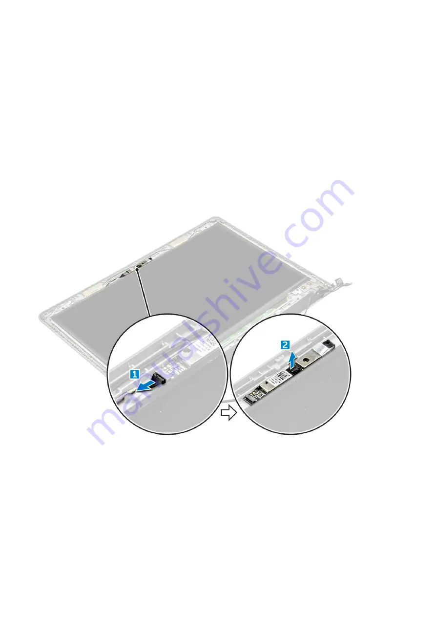
3. To remove the camera:

a. Disconnect the camera cable from the camera [1].
b. Remove the camera from the display assembly [2].

Installing the camera

1. Install the camera into the slot on the display assembly.
2. Connect the camera cable.
3. Install the:

a.

display bezel

b.

display assembly

c.

WLAN Card

d.

base cover

e.

keyboard

f.

optical drive

42

Disassembly and reassembly

Содержание 3568

Страница 1: ...Dell Vostro 15 3568 Owner s Manual Regulatory Model P63F Regulatory Type P63F002 September 2021 Rev A04 ...

Страница 2: ... pérdida de datos y le explica cómo evitar el problema AVISO Un mensaje de AVISO indica el riesgo de daños materiales lesiones corporales o incluso la muerte 2018 2021 Dell Inc o sus subsidiarias Todos los derechos reservados Dell EMC y otras marcas comerciales son marcas comerciales de Dell Inc o sus filiales Otras marcas comerciales pueden ser marcas comerciales de sus respectivos propietarios ...

Страница 3: ...optical drive bracket 15 Installing the optical drive bracket 16 Installing the optical drive 16 Keyboard lattice and Keyboard 16 Removing the keyboard 16 Installing the keyboard 18 Cubierta de la base 18 Removing the base cover 18 Installing the base cover 21 Hard drive 21 Removing the hard drive assembly 21 Removing the hard drive from the hard drive bracket 22 Installing the hard drive into the...

Страница 4: ... Installing the display assembly 40 Embellecedor de la pantalla 41 Removing the display bezel 41 Installing the display bezel 41 Camera 42 Removing the camera 42 Installing the camera 42 Panel de la pantalla 43 Removing the display panel 43 Installing the display panel 44 Bisagras de la pantalla 44 Removing the display hinges 44 Installing the display hinges 45 Touchpad 45 Removing the touchpad 45...

Страница 5: ...10 58 Identificación de la unidad de disco duro en Windows 8 58 Identificación de la unidad de disco duro en Windows 7 58 Acceso a la configuración del BIOS 58 USB features 59 HDMI 1 4 61 Características de la cámara 61 Identificación de la cámara en Administrador de dispositivos en Windows 10 61 Identificación de la cámara en el Administrador de dispositivos en Windows 8 62 Identificación de la c...

Страница 6: ...Chapter 6 Technical specifications 77 Chapter 7 Contacting Dell 81 6 Contents ...

Страница 7: ... warranty Read and follow the safety instructions that came with the product PRECAUCIÓN To avoid electrostatic discharge ground yourself by using a wrist grounding strap or by periodically touching an unpainted metal surface that is grounded to ground yourself before you touch the computer to perform any disassembly tasks PRECAUCIÓN Handle components and cards with care Do not touch the components...

Страница 8: ... from the appropriate slots Apagado del equipo Turning off your Windows PRECAUCIÓN To avoid losing data save and close all open files and exit all open programs before you turn off your computer 1 Click or tap 2 Click or tap and then click or tap Shut down NOTA Ensure that the computer and all attached devices are turned off If your computer and attached devices did not automatically turn off when...

Страница 9: ...tivos externos como un replicador de puerto o la base para medios y vuelva a colocar las tarjetas como una tarjeta ExpressCard 2 Conecte los cables telefónicos o de red al equipo PRECAUCIÓN Para conectar un cable de red enchúfelo primero en el dispositivo de red y después en el equipo 3 Conecte el equipo y todos los dispositivos conectados a la toma eléctrica 4 Encienda el equipo Trabajo en el equ...

Страница 10: ...pantalla Embellecedor de la pantalla Camera Panel de la pantalla Bisagras de la pantalla Touchpad Reposamanos Herramientas recomendadas Los procedimientos de este documento requieren el uso de las siguientes herramientas Destornillador Phillips núm 0 Destornillador Phillips núm 1 Un objeto puntiagudo de plástico Screw size list Table 1 Vostro 15 3562 screw size list Component M2L3 M2 5L8 M2L2 Bi g...

Страница 11: ...2L2 Bi g head05 M2L5 M2 5L2 5 Big head M3L3 M2L3 M2L2 Hard drive bracket 4 WLAN card 1 System fan 2 System board 2 I O board 1 Power connector 1 Display assembly 3 Display panel 4 Hinge 6 Power button board 1 Touchpad 3 4 Vista del chasis Vista frontal abierto Disassembly and reassembly 11 ...

Страница 12: ...ador luminoso de estado de la batería y de alimentación Indicador luminoso de actividad del disco duro Left view 1 Power connector 2 Network connector No LED indicator 3 VGA connector 4 HDMI 1 4 connector 5 USB 3 1 Gen 1 connector 6 USB 3 1 Gen 1 connector 12 Disassembly and reassembly ...

Страница 13: ...Vista del reposamanos 1 Botón de encendido 2 Teclado 3 Reposamanos 4 Superficie táctil Right view 1 SD card reader 2 Universal audio port Disassembly and reassembly 13 ...

Страница 14: ...ior del equipo 2 Para extraer la batería a Deslice los pestillos de liberación para desbloquear la batería 1 b Extraiga la batería del equipo 2 Instalación de la batería 1 Inserte la batería en la ranura y presiónela hasta que encaje en su lugar 2 Siga los procedimientos que se describen en Después de manipular el interior del equipo 14 Disassembly and reassembly ...

Страница 15: ...he tab in the direction of the arrow indicated on the chassis 2 c Slide the optical drive out of the computer 3 Removing the optical drive bracket 1 Follow the procedure in Before working inside your computer 2 Remove the a battery b optical drive 3 To remove the optical drive from the bracket a Remove the single M2L2 Big head05 screw that secures the optical drive bracket b Remove the optical dri...

Страница 16: ...to place 2 Tighten the two M2L3 screws to secure the optical drive to the computer 3 Install the battery 4 Follow the procedure in After working inside your computer Keyboard lattice and Keyboard Removing the keyboard 1 Follow the procedure in Before working inside your computer 2 Remove the battery 3 To remove the keyboard a Using a plastic scribe release the five tabs from the slots located abov...

Страница 17: ...4 To remove the keyboard cable a Disconnect the keyboard cable from the system board b Remove the keyboard from the computer Disassembly and reassembly 17 ...

Страница 18: ...Follow the procedure in After working inside your computer Cubierta de la base Removing the base cover 1 Follow the procedure in Before working inside your computer 2 Remove the a battery b optical drive c keyboard 3 To remove the base cover a Disconnect the optical drive connector and lift it to remove it from the system board 1 b Remove the five M2L5 screws that secure the base cover 2 18 Disass...

Страница 19: ...4 Flip the computer and remove the screws 3 screws M2L2 2 screws M2L2 8 screws M2 5L8 that secure the base cover to the computer Disassembly and reassembly 19 ...

Страница 20: ...5 To remove the base cover a Use a scribe to pry the edges of the base cover 1 b Lift the base cover and remove it from the computer 2 20 Disassembly and reassembly ...

Страница 21: ... computer over 5 Open the display and connect the optical drive connector to the system board 6 Tighten the five M2L5 screws to secure the base cover to the palm rest 7 Install the a keyboard b optical drive c battery 8 Follow the procedure in After working inside your computer Hard drive Removing the hard drive assembly 1 Follow the procedure in Before working inside your computer 2 Remove the a ...

Страница 22: ...ard drive from the hard drive bracket 1 Follow the procedure in Before working inside your computer 2 Remove the a battery b optical drive c keyboard d base cover e hard drive assembly 3 To remove the hard drive from the hard drive assembly a Pull the hard drive cable connector to remove it from the hard drive 1 b Remove the four M3L3 screws that secure the hard drive bracket to the hard drive 2 c...

Страница 23: ... working inside your computer Installing the hard drive assembly 1 Insert the hard drive assembly into the slot on the computer 2 Tighten the four M2L3 screws to secure the hard drive assembly to the computer 3 Connect the hard drive cable to the connector on the system board 4 Install the a base cover b keyboard c optical drive d battery 5 Follow the procedures in After working inside your comput...

Страница 24: ...ng the WLAN card 1 Install the WLAN card to the connector on the system board 2 Connect the WLAN cables to the connectors on the WLAN card 3 Place the securing tab on the WLAN card and tighten the M2L3 screw on the computer 4 Install the a base cover b keyboard c optical drive d battery 5 Follow the procedure in After working inside your computer Memory modules Removing the memory module 1 Follow ...

Страница 25: ...e from the system board 2 Instalación del módulo de memoria 1 Inserte el módulo de la memoria en el zócalo de la memoria 2 Presione el módulo de memoria hasta que los ganchos de retención lo fijen 3 Coloque a la cubierta de la base b el teclado c unidad óptica d la batería 4 Siga los procedimientos que se describen en Después de manipular el interior del equipo Disassembly and reassembly 25 ...

Страница 26: ...ic scribe to lift the battery out of the slot 1 2 Instalación de la batería de tipo botón 1 Inserte la batería de tipo botón en la ranura para la batería 2 Presione la batería hasta que encaje en su lugar 3 Coloque a la batería b el teclado c unidad óptica d la batería 4 Siga los procedimientos que se describen en Después de manipular el interior del equipo 26 Disassembly and reassembly ...

Страница 27: ...eath the hinge 3 d Remove the single screw M2L2 Big head07 that secures the power button board to the chassis 4 e Peel the system board cable from the chassis and then peel the tape that holds the power button board f Slide the Power button board away from the chassis Installing the power button board 1 Place the button board on the chassis 2 Affix the tape that holds the power button board 3 Affi...

Страница 28: ...ur computer 2 Remove the a battery b optical drive c keyboard d base cover 3 To remove the heat sink a Loosen the four captive screws that secure the heat sink to the system board 1 2 3 4 NOTE Loosen the screws in the order of the callout numbers 1 2 3 4 These screws are retention screws and cannot be fully removed b Remove the heat sink from the system board 5 Installing the heat sink 1 Align the...

Страница 29: ...king inside your computer System fan Removing the system fan 1 Follow the procedure in Before working inside your computer 2 Remove the a battery b optical drive c keyboard d base cover 3 To remove the system fan a Disconnect the system fan connector cable from the system board 1 b Remove the two M2L5 screws that secure the system fan to the computer 2 c Lift and remove the system fan from the cha...

Страница 30: ... the a base cover b keyboard c optical drive d battery 5 Follow the procedures in After working inside your computer Altavoz Removing the speakers 1 Follow the procedure in Before working inside your computer 2 Remove the a battery b optical drive c keyboard d base cover 3 To remove the speakers a Disconnect the speaker cable from the computer 1 b Remove the speakers from the computer 2 30 Disasse...

Страница 31: ... Install the a base cover b keyboard c optical drive d battery 4 Follow the procedure in After working inside your computer Placa base Removing the system board 1 Follow the procedure in Before working inside your computer 2 Remove the a battery b optical drive c keyboard d base cover e WLAN card Disassembly and reassembly 31 ...

Страница 32: ...m the computer 1 2 4 Lift the locking tab to disconnect the following cables a hard drive connector 1 b power connector 2 c remove the adhesive tape 3 d lift the locking tab and disconnect the eDP connector 4 e speaker 5 f touchpad connector 6 g I O connector 7 32 Disassembly and reassembly ...

Страница 33: ...5 Remove the two M2L3 screws that secure the system board to the computer 1 and lift the system board 2 Disassembly and reassembly 33 ...

Страница 34: ... Flip the system board 7 To remove the system board a Peel the adhesive tape 1 b Unlock the tab and disconnect the power cable 2 c Remove the system board from the computer 34 Disassembly and reassembly ...

Страница 35: ...the computer 6 Tighten the display hinge screw to the computer 7 Connect the following cables to the system board a hard drive connector b touchpad connector c speaker connector d I O connector e eDP connector f power connector 8 Install the a system fan b heat sink c memory module d WLAN Card e base cover f keyboard g optical drive h battery 9 Follow the procedure in After working inside your com...

Страница 36: ...ve assembly 3 To remove the Input Output board I O board a Disconnect the I O board cable 1 b Remove the M2L3 screw and lift I O board from the computer 2 3 Installing the Input Output board 1 Place the I O board on the computer 2 Connect the input output I O board cable and tighten the M2L3 screw 3 Install the a hard drive assembly b base cover c keyboard 36 Disassembly and reassembly ...

Страница 37: ...orking inside your computer 2 Remove the a battery b optical drive c keyboard d base cover e hard drive assembly f WLAN card g memory module h heat sink i system fan j system board 3 To remove the power connector a Unroute the cable 1 b Remove the single M2x2 Big head 07 screw that secures the power connector to the computer 2 c Lift the power connector 3 Disassembly and reassembly 37 ...

Страница 38: ...f hard drive assembly g base cover h keyboard i optical drive j battery 5 Follow the procedure in After working inside your computer Ensamblaje de la pantalla Removing the display assembly 1 Follow the procedure in Before working inside your computer 2 Remove the a battery b optical drive c keyboard d base cover e WLAN card 3 To remove the display assembly a Unroute the WLAN cable 1 b Peel the adh...

Страница 39: ...r 5 To remove the display assembly NOTE Place the chassis on the edge of a table with the display facing down a Remove the three M2 5L8 screws that secure the display hinge to the computer 1 Disassembly and reassembly 39 ...

Страница 40: ...eDP cable to the connector on the system board and lock the locking tab 3 Affix the adhesive tape to secure the eDP cable 4 Route the WLAN and display assembly cables through the cable securing tabs 5 Tighten the display hinges three M2 5L8 screws to secure the display assembly 6 Install the a WLAN Card b base cover c keyboard d optical drive e battery 7 Follow the procedure in After working insid...

Страница 41: ...release the tabs on the edges to release the display bezel from the display assembly b Remove the display bezel display assembly Installing the display bezel 1 Place the display bezel on the display assembly 2 Press the display bezel on the edges until it snaps onto the display assembly 3 Install the a display assembly b WLAN Card c base cover d keyboard e optical drive f battery 4 Follow the proc...

Страница 42: ...embly g display bezel 3 To remove the camera a Disconnect the camera cable from the camera 1 b Remove the camera from the display assembly 2 Installing the camera 1 Install the camera into the slot on the display assembly 2 Connect the camera cable 3 Install the a display bezel b display assembly c WLAN Card d base cover e keyboard f optical drive 42 Disassembly and reassembly ...

Страница 43: ...er e WLAN card f display assembly g display bezel 3 To remove the display panel a Remove the M2 5L8 screws that secure the display panel to the display assembly 1 b Lift the display panel to access the cables underneath 2 4 To disconnect the cable a Remove the tape that secures the eDP cable to the display panel 1 b Lift the locking tab and remove the eDP cable 2 c Remove the display panel from th...

Страница 44: ...panel to the display assembly 5 Install the a display bezel b display assembly c WLAN Card d base cover e keyboard f optical drive g battery 6 Follow the procedure in After working inside your computer Bisagras de la pantalla Removing the display hinges 1 Follow the procedure in Before working inside your computer 2 Remove the a battery b optical drive c keyboard d base cover e WLAN card 44 Disass...

Страница 45: ...es 1 Tighten the six M2 5L2 5 screws to secure the display hinges to the display assembly 2 Install the a display panel b display bezel c display assembly d WLAN Card e base cover f keyboard g optical drive h battery 3 Follow the procedure in After working inside your computer Touchpad Removing the touchpad 1 Follow the procedure in Before working inside your computer 2 Remove the a battery Disass...

Страница 46: ...acket a Remove the M2L3 screw that secures the screw support bracket to the computer 1 b Remove the bracket from the computer 2 4 To remove the touchpad support bracket a Remove the conductive tapes 1 b Remove the two M2L3 screws that secure the touchpad support bracket to the touchpad board 2 c Lift and remove the touchpad support bracket 3 46 Disassembly and reassembly ...

Страница 47: ...5 To remove the touchpad board a Remove the four M2L2 screws that secure the touchpad board to the computer 1 b Lift and remove the touchpad board 2 Disassembly and reassembly 47 ...

Страница 48: ...ink d speaker e memory module f WLAN Card g hard drive assembly h base cover i keyboard j optical drive k battery 7 Follow the procedure in After working inside your computer Reposamanos Replacing the palmrest 1 Follow the procedure in Before working inside your computer 2 Remove the a battery b optical drive c keyboard d base cover e hard drive assembly f WLAN card g memory module h power button ...

Страница 49: ... board c power connector port d I O board e speaker f system fan g heat sink h power button board i memory module j WLAN Card k hard drive assembly l base cover m keyboard n optical drive o battery 3 Follow the procedure in After working inside your computer Disassembly and reassembly 49 ...

Страница 50: ...e i7 series Intel Celeron NOTE The clock speed and performance varies depending on the workload and other variables Identificación de los procesadores en Windows 10 1 Toque Buscar en Internet y en Windows 2 Escriba Administrador de dispositivos 3 Toque Procesador Se muestra la información básica del procesador Identificación de procesadores en Windows 8 1 Toque Buscar en Internet y en Windows 2 Es...

Страница 51: ...lic en Inicio Panel de control Administrador de dispositivos 2 Seleccione Procesador Se muestra la información básica del procesador Verificación del uso del procesador en Administrador de tareas 1 Mantenga pulsada la barra de tareas 2 Seleccione Iniciar Administrador de tareas Tecnología y componentes 51 ...

Страница 52: ...arra de tareas 2 Seleccione Iniciar Administrador de tareas Se muestra la ventana del Administrador de tareas de Windows 3 Haga clic en la pestaña Rendimiento en la ventana del Administrador de tareas de Windows Se muestra la información sobre el rendimiento del procesador 4 Haga clic en Abrir monitor de recursos Conjunto de chips Todos los portátiles se comunican con la CPU a través del conjunto ...

Страница 53: ...para su portátil 8 Después de finalizar la descarga vaya a la carpeta donde guardó el archivo del controlador 9 Haga clic dos veces en el icono del archivo del controlador del conjunto de chips y siga las instrucciones que aparecen en pantalla Identificación del conjunto de chips en el Administrador de dispositivos en Windows 10 1 Haga clic en Todas las configuraciones en la barra de accesos de Wi...

Страница 54: ...dispositivos 2 Amplíe Dispositivos del sistema y busque el conjunto de chips Controladores del conjunto de chips Intel Compruebe si los controladores del conjunto de chips de Intel ya están instalados en el portátil Tabla 2 Controladores del conjunto de chips Intel Antes de la instalación Después de la instalación 54 Tecnología y componentes ...

Страница 55: ... con una resolución máxima de 1366 x 768 píxeles Identificación del adaptador de pantalla 1 Inicie el acceso a Buscar y seleccione Configuración 2 Escriba Administrador de dispositivos en el cuadro de búsqueda y a continuación toque Administrador de dispositivos en el panel izquierdo 3 Amplíe Adaptadores de pantalla Se muestran los adaptadores de pantalla Rotación de la pantalla 1 Mantenga pulsada...

Страница 56: ...splácese hacia abajo en la página y seleccione el controlador de gráficos que desea instalar 7 Toque Descargar archivo para descargar el controlador de gráficos para su portátil 8 Después de finalizar la descarga vaya a la carpeta donde guardó el archivo del controlador de gráficos 9 Haga clic dos veces en el icono del archivo del controlador de gráficos y siga las instrucciones que aparecen en pa...

Страница 57: ...ño de microfibra para eliminar cualquier rastro de polvo visible y elimine con cuidado las partículas de suciedad 3 Para limpiar la pantalla y mantenerla en perfectas condiciones clara y nítida es necesario utilizar kits de limpieza adecuados NOTA No aplique soluciones de limpieza directamente en la pantalla aplíquelas al paño de limpieza 4 Limpie suavemente la pantalla con un movimiento circular ...

Страница 58: ...o aparece bajo Unidades de disco Identificación de la unidad de disco duro en Windows 7 1 Haga clic en Inicio Panel de control Administrador de dispositivos La unidad de disco duro aparece bajo Unidades de disco 2 Amplíe Unidades de disco Acceso a la configuración del BIOS 1 Encienda o reinicie el portátil 2 Cuando aparezca el logotipo de Dell realice una de las siguientes acciones para acceder al...

Страница 59: ... nutshell USB 3 1 Gen 1 features are as follows Higher transfer rates up to 5 Gbps Increased maximum bus power and increased device current draw to better accommodate power hungry devices New power management features Full duplex data transfers and support for new transfer types Backward USB 2 0 compatibility New connectors and cable The topics below cover some of the most commonly asked questions...

Страница 60: ...ctive it s easy to imagine that with 5 10 times the bandwidth available USB video solutions should work that much better Single link DVI requires almost 2Gbps throughput Where 480Mbps was limiting 5Gbps is more than promising With its promised 4 8Gbps speed the standard will find its way into some products that previously weren t USB territory like external RAID storage systems Listed below are so...

Страница 61: ...onal color models used in digital photography and computer graphics 4K Support Enables video resolutions far beyond 1080p supporting next generation displays that will rival the Digital Cinema systems used in many commercial movie theaters HDMI Micro Connector A new smaller connector for phones and other portable devices supporting video resolutions up to 1080p Automotive Connection System New cab...

Страница 62: ...ontrol Administrador de dispositivos 2 Expanda Dispositivos de imagen Inicio de la cámara Para iniciar la cámara abra una aplicación que utilice la cámara Por ejemplo si toca el software Dell Webcam Central o el software Skype que se envía con el portátil la cámara se encenderá De forma similar si está conversando en Internet y la aplicación solicita acceder a la cámara web la cámara web también s...

Страница 63: ...ra en la lista aplicaciones 3 Si la aplicación de la cámara no está disponible en la lista aplicaciones búsquela Memory features This Laptop supports 4 GB to 16 GB 2133 MHz DDR4 SoDIMM 2 slot Tecnología y componentes 63 ...

Страница 64: ... el panel izquierdo seleccione Configuración General Información del sistema La información de la memoria se muestra en el panel derecho Testing memory using ePSA 1 Turn on or restart your laptop 2 Perform one of the following actions after the Dell logo is displayed With keyboard Press F2 Without keyboard Press and hold the Volume Up button when the Dell logo is displayed on the screen When the F...

Страница 65: ...up by pressing F2 key Bring up the one time boot menu by pressing F12 key The one time boot menu displays the devices that you can boot from including the diagnostic option The boot menu options are Removable Drive if available STXXXX Drive NOTE XXXX denotes the SATA drive number Optical Drive if available SATA Hard Drive if available Diagnostics NOTE Choosing Diagnostics displays the SupportAssis...

Страница 66: ...reen Turn offf on Wireless Fn PgUp Page up Fn Pgdn Page down Fn Home Home Fn End End F1 Mute audio F2 Decrease volume F3 Increase volume F4 Previous track F5 Play Pause F6 Next track F8 Extended display F9 Search F10 Toggle Keyboard Backlight Brightness optional F11 Decrease brightness F12 Increase brightness Fn Lock only switches primary and secondary behavior on F1 F12 F7 will behave the same be...

Страница 67: ...stema operativo Las opciones son Windows Boot Manager Administrador de inicio de Windows De manera predeterminada todas las opciones están seleccionadas También puede anular la selección de cualquier opción o cambiar el orden de inicio Boot List Option Permite cambiar la opción de la lista de inicio Legacy Heredado UEFI Advanced Boot Options Esta opción permite la carga de la ROM opcional heredada...

Страница 68: ...entes dispositivos Enable Camera Activar cámara Enable Secure Digital SD Card Activar tarjeta Secure Digital SD NOTA Todos los dispositivos están activados de forma predeterminada Tabla 9 Vídeo Opción Descripción LCD Brightness Permite ajustar el brillo en función de la fuente de energía On Battery Batería u On AC CA NOTA La configuración de vídeo solo estará visible cuando haya instalado una tarj...

Страница 69: ...cuando está establecida una contraseña de administrador Si está desactivada las opciones de configuración están bloqueadas por la contraseña de administrador UEFI Capsule Firmware Updates Permite controlar si el sistema permite las actualizaciones del BIOS a través de paquetes de cápsulas de actualización UEFI Configuración predeterminada Enable Activado TPM 2 0 Security Permite activar el módulo ...

Страница 70: ...archivo seleccionado por el usuario Replace from File Reemplazar desde archivo reemplaza la clave actual con una clave del archivo seleccionado por el usuario Append from File Anexar desde archivo añade la clave a la base de datos actual desde el archivo seleccionado por el usuario Delete Eliminar elimina la clave seleccionada Reset All Keys Reestablecer todas las claves reestablece a la configura...

Страница 71: ...ón predeterminada la opción está activada Hyper Thread Control Permite activar o desactivar el controlador HyperThreading en el procesador Disabled Desactivado Enabled Activado Configuración predeterminada la opción está activada Tabla 14 Power Management Opción Descripción AC Behavior Permite habilitar o deshabilitar el encendido automático del equipo cuando se conecta un adaptador de CA Configur...

Страница 72: ...encias del adaptador Fn Lock Option Permite que la combinación de teclas de acceso rápido Fn Esc alterne el comportamiento principal de F1 a F12 entre la función estándar y las funciones secundarias Lock Mode Disable Standard Modo de bloqueo de desactivación estándar Esta opción está activada de forma predeterminada Lock Mode Enable Secondary Modo de bloqueo activado secundario Fastboot Permite ac...

Страница 73: ...OST del programa de configuración del sistema BIOS Tabla 20 SupportAssist System Resolution Opción Descripción Auto OS Recovery Threshold Permite controlar el flujo para inicio automático del sistema SupportAssist Las opciones son Off Apagado 1 2 activado de forma predeterminada 3 SupportAssist OS Recovery Permite recuperar el sistema operativo SupportAssist desactivado de forma predeterminada Upd...

Страница 74: ...assword that you must enter to access and make changes to the BIOS settings of your computer You can create a system password and a setup password to secure your computer PRECAUCIÓN The password features provide a basic level of security for the data on your computer PRECAUCIÓN Anyone can access the data stored on your computer if it is not locked and left unattended NOTA System and setup password...

Страница 75: ... and press Enter The System Security screen is displayed 2 In the System Security screen verify that Password Status is Unlocked 3 Select System Password alter or delete the existing system password and press Enter or Tab 4 Select Setup Password alter or delete the existing setup password and press Enter or Tab NOTA If you change the System and or Setup password re enter the new password when prom...

Страница 76: ...action Always ensure that you are present at the computer terminal when the diagnostic tests are performed Temas Running the ePSA Diagnostics Running the ePSA Diagnostics Invoke diagnostics boot by either of the methods that are suggested below 1 Power on the computer 2 As the computer boots press the F12 key when the Dell logo is displayed 3 In the boot menu screen use Up Down arrow key to select...

Страница 77: ...ssor 4405U Intel Celeron Processor 3855U L2 cache 2 MB Table 24 Memory specifications Feature Specification Memory connector Two internally accessible DDR4 SoDIMM connectors Memory size per slot 4 GB and 8 GB 4 GB 1 x 4 GB 8 GB 1 x 8 GB 8 GB 2 x 4 GB 16 GB 2 x 8 GB Memory speed 2133 Mhz Minimum memory 4 GB Maximum memory 16 GB Table 25 Storage specifications Feature Specification M 2 SSD SATA 3 0 ...

Страница 78: ...fications Feature Specification Network adapter 10 100 1000 Mbps Ethernet LAN on Motherboard LOM Wireless Wi Fi 802 11 b g n Bluetooth 4 1 Table 30 Ports and connectors specifications Feature Specification Audio One headphone microphone combo port headset Video HDMI 1 4a Full size without 4k2k output Dedicated VGA D SUB connector on board Network adapter One RJ 45 port USB Two USB 3 0 ports One US...

Страница 79: ... 105 Pitch X 19 05 mm Y 18 05 mm Travel distance 3 3 mm Table 33 Touchpad specifications Feature Specification Active Area X axis 105 00 mm 4 13 inches Y axis 80 00 mm 3 14 inches Table 34 Battery specifications Feature Specification Type 4 cell smart lithium ion 47 WHr Dimensions Height 20 00 mm 0 78 in Width 270 00 mm 10 63 inches Depth 37 50 mm 1 47 inches Weight 0 25 kg 0 56 lb Life span 300 d...

Страница 80: ...ication Height 23 65 mm 0 93 inches Width 380 00 mm 14 96 inches Depth 260 30 mm 10 24 inches Weight 2 29 kg 5 04 lb Table 37 Environmental specifications Feature Specification Temperature Operating 0 C 35 C 32 F 95 F Storage 40 C 65 C 40 F 149 F Relative humidity maximum Operating 10 to 90 non condensing Storage 0 to 95 non condensing Altitude maximum Operating 15 2 m to 30482000 m 50 to 10 00065...

Страница 81: ... service options Availability varies by country and product and some services may not be available in your area To contact Dell for sales technical support or customer service issues 1 Go to Dell com support 2 Select your support category 3 Verify your country or region in the Choose a Country Region drop down list at the bottom of the page 4 Select the appropriate service or support link based on...

Отзывы: