background image

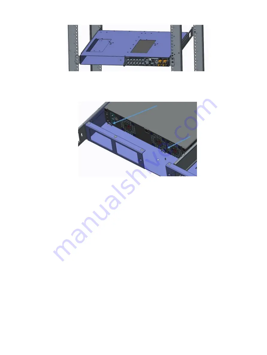
Figure 17. Install an S4112-ON Series switch

The switch is fully inserted when it hits the stop feature on the dual tray. The front switch latch snaps the switch into place.

Figure 18. Dual-tray stop feature

If you are installing two switches, insert the second switch in the open dual-tray slot.

Switch removal

Remove the switch from the dual tray from the front of the four-post rack.

Push in the front switch latches according to the latch arrows and pull out the switch.

24

S4112–ON Series installation

Содержание S4112F-ON

Страница 1: ...S4112 ON Series Installation Guide November 2018...

Страница 2: ...to hardware or loss of data and tells you how to avoid the problem WARNING A WARNING indicates a potential for property damage personal injury or death Copyright 2018 Dell Inc or its subsidiaries All...

Страница 3: ...et placement 17 Rack mounting 18 Switch ground 18 Fans and airflow 18 Fan combinations 18 Power 19 Storing components 19 4 S4112 ON Series installation 20 Unpack 20 Unpack steps 20 Ground cable 21 Rac...

Страница 4: ...n 38 IEEE standards 39 Agency compliance 40 USA Federal Communications Commission statement 40 European Union EMC directive conformance statement 40 Japan VCCI compliance for class A equipment 41 Kore...

Страница 5: ...RNING When no cable is connected visible and invisible laser radiation may be emitted from the aperture of the optical transceiver ports Avoid exposure to laser radiation Do not stare into open apertu...

Страница 6: ...UTION The Caution icon signals information about situations that could result in equipment damage or loss of data WARNING The Warning icon signals information about hardware handling that could result...

Страница 7: ...8 QSFP28 ports The S4112F ON supports 1 10 25 40 50 100GbE with 12 fixed SFP ports to implement 1GbE and 10GbE and three fixed QSFP28 ports to implement 4x10 4x25 2x50 40 and 100GbE The S4112T ON supp...

Страница 8: ...ON Series AC I O side view 1 Twelve SFP ports 2 Micro USB B console port 3 Stack ID 4 Ethernet management port 5 RS 232 console port 6 AC PSUs 7 RJ 45 management port 8 Three QSFP28 ports Figure 4 S4...

Страница 9: ...nd DC fan side view 1 Ground holes 2 Fans Features The S4112 ON Series S4112F ON and S4112T ON offers the following features S4112F ON 12 fixed 1 10GbE SFP ports and 3 fixed 100GbE QSFP28 ports S4112T...

Страница 10: ...ribes open networking installation environment ONIE LED behaviors Some LED behaviors may change after you install your software LED behavior The following S4112 ON Series switch LED behavior displays...

Страница 11: ...ellow Noncritical system error fan failure or power supply failure Power LED Off No power Solid green Normal Solid yellow POST is in process Flashing yellow Power Supply failure or loss of power redun...

Страница 12: ...peed 10G on an SFP port Solid yellow Link operating at a lower speed 1G on an SFP port Activity LED Off No link Flashing green Port activity Solid blue 1 second on off Port beacon NOTE There are four...

Страница 13: ...wire clips for AC power cables Dual tray or single rails not included Screws for rack installation not included 1 and 2 Phillips screwdrivers not included Torx screwdriver not included Ground cable sc...

Страница 14: ...SFP ports 7 segment stacking indicator 1 micro USB B console port 1 USB type A port 1 RJ 45 10 100 1000 Base T Ethernet management port 2 AC or DC PSUs and 3 integrated fans S4112T ON AC or DC Reverse...

Страница 15: ...Figure 9 S4112 ON Series AC luggage tag 1 MAC address 2 Service tag 3 System QRL 4 QRL S4112 ON Series switch 15...

Страница 16: ...Figure 10 S4112 ON Series DC luggage tag 1 MAC address 2 Service tag 3 System QRL 4 QRL 16 S4112 ON Series switch...

Страница 17: ...ets the following safety requirements Near an adequate power source Connect the switch to the appropriate branch circuit protection according to your local electrical codes Environmental or switch loc...

Страница 18: ...attached to the switch Before you install the DC switch in the dual tray attach the ground lug and bracket to the switch using the included screws and then attach the DC ground wire to the ground lug...

Страница 19: ...er cords Before servicing ensure all power cords are disconnected CAUTION On the AC switch use the power supply cable as the main disconnect device Ensure that the socket outlet is located installed n...

Страница 20: ...e Topics Unpack Ground cable Rack or cabinet installation Half RU front rack installation Switch installation Optics installation Switch power up After switch installation Switch replacement Unpack NO...

Страница 21: ...nd lug and bracket to the switch using the M4 screws 4 Using one of the two M4 threaded holes attach the ground cable to the lug Use the M4 screw with a captive internal tooth lock washer Torque the s...

Страница 22: ...tion NOTE Do not install the dual tray in a two post rack To install the half RU switch Attach the rails to the dual tray Install the dual tray in the rack Install the switch in the dual tray 1 Remove...

Страница 23: ...or each rack post Figure 15 Attach the dual tray rear to the 4 post rack rear 8 Tighten all mounting screws to securely mount the dual tray into the 4 post rack Figure 16 Secure the dual tray in the 4...

Страница 24: ...he switch into place Figure 18 Dual tray stop feature 2 If you are installing two switches insert the second switch in the open dual tray slot Switch removal Remove the switch from the dual tray from...

Страница 25: ...e CAUTION ESD damage can occur if components are mishandled Always wear an ESD preventive wrist or heel ground strap when handling the S4112 ON Series and its components WARNING When working with opti...

Страница 26: ...l other power cables separately NOTE ESD damage can occur if components are mishandled Always wear an ESD preventive wrist or heel ground strap when handling the S4112 ON Series switch and its compone...

Страница 27: ...ed switch show os version If the software versions do not match upgrade the replacement switch software using the procedure included with the firmware download 7 Copy the backed up switch configuratio...

Страница 28: ...the power supply to the appropriate branch circuit protection as defined by your local electrical codes and verify that the remote power source complies with the switch input power specifications NOTE...

Страница 29: ...oltages Do not attempt to operate this switch with the safety cover removed CAUTION Remove the power cable from the PSU before removing the PSU Also do not connect the power cable before you insert th...

Страница 30: ...n the I O side of the switches Solid green Input is OK Flashing yellow There is a fault with the PSU Flashing green System update Off PSU is off DC power connections Each DC PSU comes with a connector...

Страница 31: ...e screws that secures the bare wires into the wiring block 4 Secure the site s DC power source wires to the other side of the wiring block see steps 1 and 3 WARNING Do not cross the wires 5 Insert the...

Страница 32: ...O panel reverse Components The following are the S4112 ON Series S4112F ON and S4112T ON fan components S4112 ON Series fan module S4112 ON Series fan module reverse Integrated fan number 1 is on the...

Страница 33: ...output may vary Topics RS 232 console port access USB B console port access USB storage Before you install an OS ONIE service discovery RS 232 console port access The RS 232 console port is on the I...

Страница 34: ...rial port Or install the DB 9 cable into other data terminal equipment DTE server hardware that you intend to use 3 Keep the default terminal settings on the console as follows 115200 baud rate No par...

Страница 35: ...control USB storage USB storage does not automatically mount The supported file system is FAT To use USB storage first mount the device using the following steps 1 Create a mount directory for the USB...

Страница 36: ...t an operating software OS or enter e to edit the commands before booting Enter c for a command line The selected entry runs automatically in the operating system Grub bootloader example GNU GRUB vers...

Страница 37: ...ting system manually from HTTP FTP or TFTP using the onie nos install URL command NOTE If you have a recovery USB plugged into your switch remove it before installing the DIAG OS using the onie nos in...

Страница 38: ...s Commission statement European Union EMC directive conformance statement Japan VCCI compliance for class A equipment Korean certification of compliance Safety standards and compliance agency certific...

Страница 39: ...048 meters Maximum non operational altitude 39 370 feet 12 000 meters Shock Dell EMC Spec SV0115 Table 10 AC power requirements Parameter Specifications Power supply 100 240 VAC 50 60 Hz Maximum curr...

Страница 40: ...ment Unauthorized changes or modification could void the user s authority to operate the equipment This device complies with Part 15 of the FCC Rules Operation is subject to the following two conditio...

Страница 41: ...ormation Technology Equipment VCCI If this equipment is used in a domestic environment radio disturbance may arise When such trouble occurs the user may be required to take corrective actions WARNING...

Страница 42: ...60825 2 Safety of Laser Products Part 2 Safety of Optical Fibre Communication Systems FDA Regulation 21CFR 1040 10 and 1040 11 IEC 60950 1 2nd Ed including all National Deviations and Group Difference...

Страница 43: ...ling of used appliances as applicable throughout the European Union This label is applied to various products to indicate that the product is not to be thrown away but rather reclaimed upon end of lif...

Страница 44: ...page and select your country from the drop down menu To obtain product specific information enter the 7 character service tag known as a luggage tag or 11 digit express service code of your switch an...

Отзывы: