


Table 41. Procedure options for AC power connection (continued)
Situation on site
Procedure
The customer’s electrician is NOT available at the installation site,
but you have access to customer-supplied, labeled, power cables
(beneath a raised floor or overhead).
Procedure B: Verify and connect
The customer’s electrician is NOT available at the installation site,
customer-supplied PDU source cables are already plugged into the
PDU and you have no access to the customer-supplied power
cables.
Procedure C: Obtain customer verification
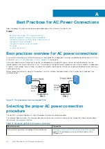
Procedure A: Working with the customer's
electrician onsite
Use this procedure if the customer’s electrician is available at the installation site.
This procedure requires three basic tasks that alternate between the customer's electrician, the Dell EMC CE and back to the customer's
electrician.
•
Task 1: Customer's electrician
•
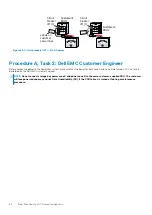
Task 2: Dell EMC Customer Engineer (CE)
•
Task 3: Customer's electrician
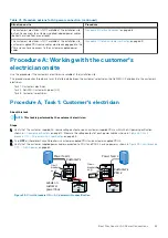
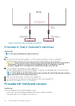
Procedure A, Task 1: Customer's electrician
About this task
NOTE:
This task is performed by the customer's electrician.
Steps
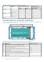
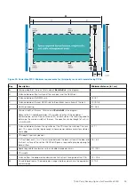
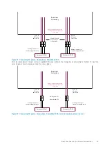
1. Verify that the customer-supplied AC source voltage output on each customer-supplied PDU is within the AC power specification
on page 70. Measure the voltage output of each power cable as shown in
breakers ON — AC power within specification
on page 63.
2. Turn
OFF
all the relevant circuit breakers in customer-supplied PDU 1 and customer-supplied PDU 2.
3. Verify that the customer-supplied power cables connected to PDU 1 and PDU 2 have no power as shown in
Customer’s
PDU 1
Customer’s
PDU 2
Circuit
breakers
on (|)
Circuit
breakers
on (|)
Circuit breakers - Numbers
27
28
29
30
Circuit breakers - Numbers
...
8
9
10
11
...
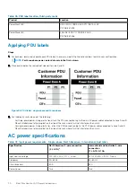
Labels on
customer
power lines
Power feed 1
Power feed 2
PDU 1
CB 28
PDU 2
CB 9
Voltmeter
TYPE PM89
CLASS 25 01
0
100
240
30
0
V
Voltmeter
TYPE PM89
CLASS 25 01
0
100
240
30
0
V
Figure 28. Circuit breakers ON — AC power within specification
Best Practices for AC Power Connections
63


