background image

Logging behavior

As with all Redundancy Policies, when a Power Supply Unit fails, a log message is generated. For the Fault Tolerant Redundancy
policy, a log message will also be recorded to note a "Loss of Redundancy". This message indicates that the system is continuing
to operate in a Non-Redundant state, and action is necessary to either restore power to a failed AC Grid or replace a failed
Power Supply Unit. Details in log messages make it possible to distinguish between these two cases. Finally, in case power-on of
a chassis component is denied due to a Power Budget Check, the denial is logged both in CMC logs and iDRAC logs (in the case
of compute sleds).

Removing a power supply unit

Prerequisites

1. Follow the safety guidelines listed in 

Safety instructions.

2. Disconnect the power cable from the power source and from the PSU you intend to remove, and then remove the cable

from the strap on the PSU handle.

CAUTION:

 The power supply is only hot-swappable if you have a redundant system with two power supplies

installed

Steps

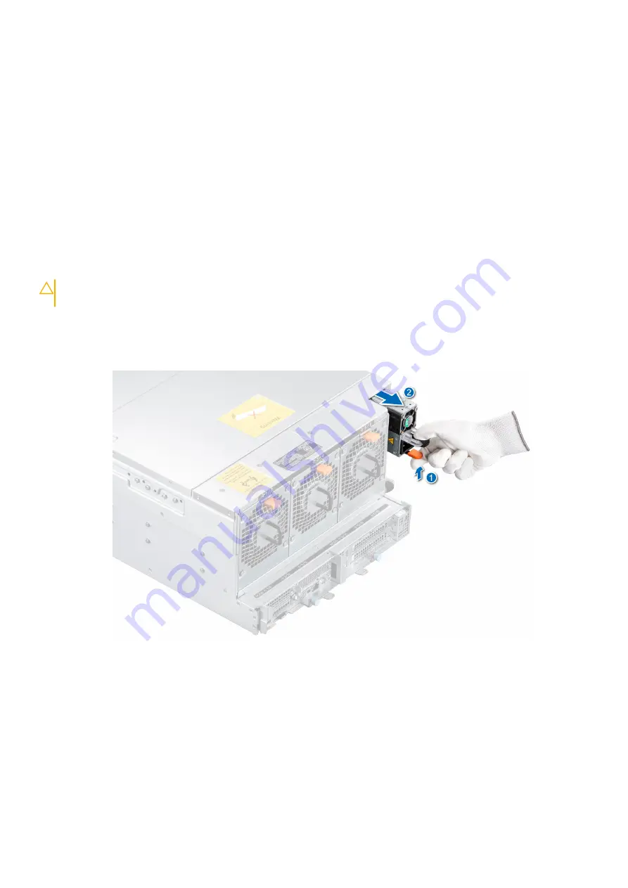
1. Press and hold the release latch.
2. Slide the PSU out of the system using the PSU handle.

Figure 21. Removing a power supply unit

Next steps

Install the PSU

Installing a power supply unit

Prerequisites

1. Follow the safety guidelines listed in 

safety instructions

.

28

Installing and removing enclosure components

Содержание PowerEdge xe7100

Страница 1: ...Dell EMC PowerEdge xe7100 Installation and Service Manual Regulatory Model B22S Series B24S Series Regulatory Type B22S001 B24S001 August 2020 Rev A00 ...

Страница 2: ...ential damage to hardware or loss of data and tells you how to avoid the problem WARNING A WARNING indicates a potential for property damage personal injury or death 2020 Dell Inc or its subsidiaries All rights reserved Dell EMC and other trademarks are trademarks of Dell Inc or its subsidiaries Other trademarks may be trademarks of their respective owners ...

Страница 3: ...ptions to download and install OS drivers 22 Downloading drivers and firmware 23 Chapter 4 Installing and removing enclosure components 24 Safety instructions 24 Before working inside your system 25 After working inside your system 25 Recommended tools 25 Dell EMC PowerEdge XE7440 and XE7420 sleds 25 Removing the sled 25 Installing the sled 26 Power supply units 27 Fault tolerant redundancy 27 Rem...

Страница 4: ...talling the PERC riser 54 Removing the PERC card 55 Installing the PERC card 56 Removing the PERC riser board 57 Installing the PERC riser board 57 Drive cage 58 Removing the 3 5 inch drive cage 58 Installing the drive cage 59 Backplanes and expander board 60 Backplane 60 3 5 inch hard drive mapping 62 Removing the 2 5 inch hard drive backplane 63 Installing the backplane 63 Removing the backplane...

Страница 5: ...agnostics and indicator codes 81 Status LED indicators 81 System health and system ID indicator codes 81 iDRAC Direct LED indicator codes 82 NIC indicator codes 82 Power supply unit indicator codes 83 Using system diagnostics 84 Dell Embedded System Diagnostics 84 Chapter 7 Documentation resources 86 Chapter 8 Getting help 88 Contacting Dell EMC 88 Documentation feedback 88 Accessing system inform...

Страница 6: ...ument provides an overview about the system information about installing and replacing components technical specifications diagnostic tools and guidelines to be followed while installing certain components 1 6 About this document ...

Страница 7: ...sh NVMe PCIe SSD User s Guide at https www dell com support Browse all Products Data Center Infrastructure Storage Adapters Controllers Dell PowerEdge Express Flash NVMe PCIe SSD Documentation Manuals and Documents NOTE All instances of SAS SATA drives are seen as drives in this document unless specified otherwise For more information about supported drives see the Drive specifications section Top...

Страница 8: ...Figure 1 PowerEdge XE chassis with XE7420 sleds PowerEdge XE7100 chassis with XE7440 sled Figure 2 PowerEdge XE chassis with XE7440 sled 8 PowerEdge XE7100 system overview ...

Страница 9: ...panel 2 Expander module 1 3 Expander module 2 4 Service tag Figure 4 Front view of expander module 1 PERC slot 2 2 5 inch SSDs 3 Pull out lever 4 Captive screw Front view of the control panel Figure 5 Front view of the control panel PowerEdge XE7100 system overview 9 ...

Страница 10: ...upply unit 2 4 Half width sled 2 5 Half width sled 1 Figure 7 Rear view of the system with FW sled 1 Cooling fan 2 Power supply unit 1 3 Power supply unit 2 4 Full width sled Inside the enclosure CAUTION This system must be operated with the system cover installed to ensure proper cooling 10 PowerEdge XE7100 system overview ...

Страница 11: ...sion switch 5 Power distribution board module Chassis manager board module 6 Fan cage 7 3 5 inch HDD slot 8 Front intrusion switch Figure 9 Inside the PowerEdge XE7440 sled 1 Sled cable kit 1 2 Motherboard bridge board 1 3 Motherboard interposer board 4 Cooling fan 5 Memory sockets 6 Dust cover for processor 2 PowerEdge XE7100 system overview 11 ...

Страница 12: ... Motherboard interposer board 11 Motherboard bridge board Locating the service Tag of your system Your system is identified by a unique Express Service Code and Service Tag number The Express Service Code and Service Tag are found on the front of the enclosure by pulling out the EST tag This information is used by Dell to route support calls to the appropriate personnel Figure 11 Locating the Serv...

Страница 13: ...System information label Express service tag Figure 12 Express service tag PowerEdge XE7100 system overview 13 ...

Страница 14: ...Service information Figure 13 Service information 14 PowerEdge XE7100 system overview ...

Страница 15: ...Service information on the rear Figure 14 Service information on the rear PowerEdge XE7100 system overview 15 ...

Страница 16: ...Configuration and layout Figure 15 Configuration and layout 16 PowerEdge XE7100 system overview ...

Страница 17: ...System touchpoints Figure 16 System touchpoints PowerEdge XE7100 system overview 17 ...

Страница 18: ...Matrix available at https i dell com sites csdocuments Business_solutions_engineering Docs_Documents en rail rack matrix pdf The document provides the information that is listed below Specific details about rail types and their functionalities Rail adjustability ranges for various rack mounting flange types Rail depth with and without cable management accessories Rack types that are supported for ...

Страница 19: ...For more information about rack installation see relevant rack installation guide at www dell com xemanuals PowerEdge XE7100 system overview 19 ...

Страница 20: ... the overall availability of Dell EMC servers iDRAC alerts you to system issues helps you to perform remote management and reduces the need for physical access to the system Options to set up iDRAC IP address To enable communication between your system and iDRAC you must first configure the network settings based on your network infrastructure The network settings option is set to DHCP by default ...

Страница 21: ... LOM mode if you have opted for a system that has the shared LOM mode enabled Options to log in to iDRAC To log in into the iDRAC Web User Interface open a browser and enter the IP address You can log in to iDRAC as iDRAC user Microsoft Active Directory user Lightweight Directory Access Protocol LDAP user In the login screen displayed if you have opted for secure default access to iDRAC enter the ...

Страница 22: ...rs and firmware section You can also choose any one of the following options to download the firmware For information about how to download the firmware see the documentation links provided in the table Table 3 Options to download firmware Option Documentation link Using Dell Remote Access Controller Lifecycle Controller iDRAC with LC www dell com idracmanuals Using Dell Repository Manager DRM www...

Страница 23: ...he web browser cache before downloading the drivers and firmware Steps 1 Go to www dell com support drivers 2 Enter the Service Tag of the system in the Enter a Dell Service Tag Dell EMC Product ID or Model field and then press Enter NOTE If you do not have the Service Tag select Detect PC to automatically detect the Service Tag or click Browse all products and navigate to your product 3 On the di...

Страница 24: ...ine or telephone service and support team Damage due to servicing that is not authorized by Dell is not covered by your warranty Read and follow the safety instructions that are shipped with your product CAUTION To ensure proper operation and cooling all bays in the system and system fans must be always populated with a component or a blank NOTE It is recommended that you always use an antistatic ...

Страница 25: ...stallation Guide relevant to your rail solutions at www dell com xemanuals 3 Reconnect the peripherals and connect the system to the electrical outlet and then power on the system Recommended tools You need the following tools to perform the removal and installation procedures Phillips 1 screwdriver Phillips 2 screwdriver Torx T30 screwdriver 5mm hex nut screwdriver Plastic scribe 1 4 inch flat bl...

Страница 26: ...uctions Steps 1 Hold the sled on both sides and slide the sled into the enclosure until the sled is locked to the enclosure 2 Push the sled lever under the sled and tighten the captive screws Figure 20 Installing the sled Next steps 1 Follow the procedure listed in After working inside the system 26 Installing and removing enclosure components ...

Страница 27: ...y is a limit on peak performance that occurs when redundancy is lost Fault Tolerant Redundancy can maintain the same conservative standards of redundancy as traditional Grid Redundancy by limiting peak power after redundancy is lost to levels which fit within the surviving Power Supply Policy control As with all Redundancy Policies while the two Power Supplies remain healthy load is shared evenly ...

Страница 28: ... Check the denial is logged both in CMC logs and iDRAC logs in the case of compute sleds Removing a power supply unit Prerequisites 1 Follow the safety guidelines listed in Safety instructions 2 Disconnect the power cable from the power source and from the PSU you intend to remove and then remove the cable from the strap on the PSU handle CAUTION The power supply is only hot swappable if you have ...

Страница 29: ...ng a new PSU wait for 15 seconds for the system to recognize the PSU and determine its status The PSU redundancy may not occur until discovery is complete Wait until the new PSU is discovered and enabled before you remove the other PSU The PSU status indicator turns green to signify that the PSU is functioning properly Cooling fans Removing a cooling fan Prerequisites WARNING Do not attempt to ope...

Страница 30: ...cooling fan 2 For more information about the fan status see the management software Installing a cooling fan Prerequisites 1 Follow the safety guidelines listed in safety instructions Steps Align the cooling fan with the fan slot on the cooling fan cage and push the cooling fan until it clicks into place 30 Installing and removing enclosure components ...

Страница 31: ...tem is powered down Allow the fan to stop spinning before removing it from the system NOTE Observe the routing of the cables when removing them from the system Route these cables properly when you replace them to prevent the cables from being pinched or crimped 1 Follow the safety guidelines listed in safety instructions 2 Follow the procedure listed in the Before working inside your system 3 Remo...

Страница 32: ...m from the system Route these cables properly when you replace them to prevent the cables from being pinched or crimped 1 Follow the safety guidelines listed in safety instructions Steps 1 Align the guide pins on the cooling fan cage with the guide holes on the chassis 2 Install the fan cage onto the chassis and push until it is firmly seated on the guide holes 3 Secure the fan cage using the five...

Страница 33: ...timal speed Removing the cooling fan board Prerequisites 1 Follow the safety guidelines listed in safety instructions 2 Follow the procedure listed in the Before working inside your system 3 Remove the cooling fans 4 Remove the cooling fan cage Steps 1 Remove the two screws securing the fan board bracket 2 Lift the fan board module from the hard disk drive back plane board Installing and removing ...

Страница 34: ...ng fan board Installing the cooling fan board Prerequisites WARNING Do not attempt to operate the system without the cooling fans NOTE Observe the routing of the cables when removing them from the system Route these cables properly when you replace them to prevent the cables from being pinched or crimped 1 Follow the safety guidelines listed in safety instructions 34 Installing and removing enclos...

Страница 35: ... back plane board 3 Secure the fan board bracket using the two screws Figure 30 Installing the cooling fan board bracket Next steps 1 Install the cooling fan cage 2 Install the cooling fans 3 Follow the procedure listed in After working inside the system 4 Check the management software to see if all the fans are rotating at the optimal speed Installing and removing enclosure components 35 ...

Страница 36: ...andle slide the expander module out of the enclosure horizontally Figure 31 Removing the expander module Next steps 1 Install the expnader module Installing the expander module Prerequisites 1 Follow the safety guidelines listed in safety instructions Steps 1 Align and slide the expander module into the chassis 2 Push the expander module pull handle 3 Tighten the captive screw NOTE Ensure both the...

Страница 37: ...inside your system 3 Remove the expander module 4 If applicable remove the 2 5 inch HDDs 5 Remove the 2 5 inch HDD backplane 6 Remove the PERC riser 7 Disconnect all the cables from the expander board NOTE Observe the routing of the cable as you remove it from the system Steps 1 Using the Phillips 2 screwdriver remove the two screws that secure the bracket to the expander module 2 Lift the bracket...

Страница 38: ...ver remove the two screws that secure the expander board to the expander module 4 Slide and lift the expander board from the expander module Figure 34 Removing the expander board Next steps Replace the expander board 38 Installing and removing enclosure components ...

Страница 39: ...nside your system Steps 1 Align and insert the expander board into the expander module 2 Tighten the two screws to secure the expander board to the module Figure 35 Installing the expander board 3 Align and insert the bracket into the expander module 4 Tighten the two screws to secure the bracket to the module Installing and removing enclosure components 39 ...

Страница 40: ... If applicable install the 2 5 inch HDDs 5 Install the expander module 6 Follow the procedure listed in After working inside the system System cover Removing the front system cover Prerequisites 1 Follow the safety guidelines listed in the Safety instruction Steps 1 Slide the two latches 2 Lift the front cover 40 Installing and removing enclosure components ...

Страница 41: ...ps Replace the system cover Installing the front system cover Prerequisites 1 Follow the safety guidelines listed in the Safety instruction Steps Lower the front cover until the latches clicks into place Installing and removing enclosure components 41 ...

Страница 42: ...oving the rear system cover Prerequisites 1 Follow the safety guidelines listed in the Safety instruction Steps 1 Slide the two latches 2 Lift the front cover Figure 39 Removing the rear system cover 42 Installing and removing enclosure components ...

Страница 43: ...til the latches clicks into place Figure 40 Rear system cover installation Removing the system cover Prerequisites 1 Follow the safety guidelines listed in the Safety instruction Steps 1 Slide the four latches and lift the front and rear system covers halfway 2 Holding front and rear system covers lift the cover away from the system Installing and removing enclosure components 43 ...

Страница 44: ...alling the system cover Prerequisites 1 Follow the safety guidelines listed in the Safety instruction Steps 1 Align and place the system cover onto the chassis 2 Lower the front and rear covers until the latches clicks into place 44 Installing and removing enclosure components ...

Страница 45: ...For drives inside the chassis remove the system cover 4 Using the management software prepare the drive for removal If the drive is online the green activity or fault indicator flashes while the drive is turning off When the drive indicators are off the drive is ready for removal For more information see the documentation for the storage controller CAUTION Before attempting to remove or install a ...

Страница 46: ...dure listed in After working inside the system 2 Install a drive carrier 3 If you are not replacing the drive immediately insert a drive blank in the empty drive slot to maintain proper system cooling Installing a drive carrier Prerequisites CAUTION Before attempting to remove or install a drive while the system is running see the documentation for the storage controller card to ensure that the ho...

Страница 47: ...n supplied with your operating system CAUTION When a replacement hot swappable drive is installed and the system is powered on the drive automatically begins to rebuild Ensure that the replacement drive is blank or contains data that you wish to overwrite Any data on the replacement drive is immediately lost after the drive is installed 1 Follow the safety guidelines listed in safety instructions ...

Страница 48: ... the drive carrier Prerequisites 1 Follow the safety guidelines listed in the Safety instruction Steps 1 Flex the drive carrier bracket outwards 2 Lift the drive out of the drive carrier Figure 47 Removing the 3 5 inch drive from the drive carrier 48 Installing and removing enclosure components ...

Страница 49: ...es 1 Follow the safety guidelines listed in the Safety instructions 2 If installed remove the drive blank Steps 1 Flex the drive carrier outwards 2 Align the screw holes on the drive with the two pins on the drive carrier and install the drive into the carrier Figure 49 Installing a 3 5 inch drive into the drive carrier Installing and removing enclosure components 49 ...

Страница 50: ...s installed CAUTION To maintain proper system cooling drive blanks must be installed in all empty drive slots CAUTION Mixing drive blanks from previous generations of PowerEdge servers is not supported Steps 1 Press the release button to open the drive carrier release handle 2 Holding the handle slide the drive blank out of the drive slot Figure 51 Removing a drive blank Next steps 1 Follow the sa...

Страница 51: ...to the drive slot and push the blank until the release button clicks into place Figure 52 Installing a 2 5 inch drive blank Power distribution board Power distribution board is also Chassis Manager Board Removing the power distribution board Prerequisites WARNING Allow the power distribution board PDB to discharge after you power off the system Handle the PDB by the edges and avoid touching the co...

Страница 52: ...ving the PDB Next steps 1 Install the PDB Installing the power distribution board Prerequisites WARNING Allow the power distribution board PDB to discharge after you power off the system Handle the PDB by the edges and avoid touching the contact surfaces of the connectors 1 Follow the safety guidelines listed in safety instructions 52 Installing and removing enclosure components ...

Страница 53: ...ect the intrusion cable to the PDB Figure 55 Installing the PDB 4 Align and lower the PDB module into the chassis 5 Replace the two screws to secure the PDB module Figure 56 Installing the PDB module Next steps 1 close the rear system cover 2 Install the power supply units 3 Follow the procedure listed in After working inside the system Installing and removing enclosure components 53 ...

Страница 54: ...le Figure 57 Removing the PERC riser Next steps Replace the PERC riser Installing the PERC riser Prerequisites 1 Follow the safety guidelines listed in safety instructions 2 Follow the procedure listed in the Before working inside your system Steps 1 Holding the edges or the touch points align the screw holes on the riser bracket with the screw hole on the expander module 2 Lower the PERC riser an...

Страница 55: ...ety guidelines listed in safety instructions 2 Follow the procedure listed in the Before working inside your system 3 Remove the expander module 4 Remove the PERC riser 5 Disconnect all the cables from the PERC card Steps Hold the PERC card by its edges and pull the card until the card edge connector disengages from the connector on the PERC riser Installing and removing enclosure components 55 ...

Страница 56: ...the card for installation NOTE For instructions see the documentation accompanying the card Steps 1 Hold the card by its edges and align the card edge connector with the PERC riser connector NOTE Ensure that the edge of the card guides through the card holder 2 Insert the card edge connector firmly into the PERC riser connector until the card is fully seated Figure 60 PERC card installation 3 if a...

Страница 57: ... card Steps 1 Using the Phillips 2 screwdriver remove the two screws that secure the PERC riser board to the PERC riser 2 Pull the PERC riser board from the riser Figure 61 Removing the PERC riser board Next steps Replace the PERC riser board Installing the PERC riser board Prerequisites 1 Follow the safety guidelines listed in safety instructions 2 Follow the procedure listed in the Before workin...

Страница 58: ...s NOTE Observe the routing of the cables on the chassis as you remove them from the system You must route these cables properly when you replace them to prevent the cables from being pinched or crimped 1 Follow the safety guidelines listed in safety instructions 2 Follow the procedure listed in the Before working inside your system 3 Remove the system cover 4 Remove all the drives 5 Remove the pow...

Страница 59: ...system before removing the backplane CAUTION You must note the number of each drive and temporarily label them before removal so that you can replace them in the same locations Follow the safety guidelines listed in safety instructions Steps 1 Insert the front rear drive cage into the enclosure aligning the drive cage with the standoffs on the chassis Installing and removing enclosure components 5...

Страница 60: ...ps 1 Install the power distribution board 2 Install the power supplies 3 Install all the drives 4 Install the system cover 5 Follow the procedure listed in After working inside the system Backplanes and expander board Backplane The following pages contain information about the backplane and middle plane connectors 60 Installing and removing enclosure components ...

Страница 61: ...4 6 SAS SATA connector 7 Fan connector 5 6 The image below shows the 2 5 inch hard drive backplane Figure 66 4 x 2 5 inch hard drive backplane 1 Midplane connector for link x8 PCIE Gen3 for 2 5 inches NVMe SSD and Link x4 SAS SATA for 2 5 inches SSD 2 Power connector for link power P12V_25_BP from SAS expander board SAS Expander board The image below shows the Expander board Installing and removin...

Страница 62: ...en3 for PERC or raid card 6 Contact power P12V_NODE with mid plane 7 Power connector for P12V_25_BP to 2 5 inches SSD backplane 8 SFF standard x8 OCulink connector 9 Riser connector for PCIe Gen3 PERC or raid card 10 JTAG connector 3 5 inch hard drive mapping The following image contains information about the 3 5 inch hard drive mapping Figure 68 3 5 inch hard drive mapping 62 Installing and remov...

Страница 63: ... pinched or crimped 1 Follow the safety guidelines listed in safety instructions 2 Follow the procedure listed in the Before working inside your system 3 Remove the expander module 4 Disconnect all the cables from the backplane Steps 1 Using the Phillips 2 screwdriver remove the two screws that secure the backplane to the expander module 2 Lift the backplane away from the expander module Figure 69...

Страница 64: ...xpander module 3 Follow the procedure listed in After working inside the system Removing the backplane midplane assembly Prerequisites NOTE To prevent damage to the drives and backplane you must remove the drives from the system before removing the backplane NOTE Observe the routing of the cable on the chassis as you remove them from the system You must route these cables properly when you replace...

Страница 65: ...rd from the chassis Figure 71 Removing the backplane midplane assembly Next steps 1 Install the hard drive backplane module Installing the backplane midplane assembly Prerequisites NOTE Observe the routing of the cable on the chassis as you remove them from the system You must route these cables properly when you replace them to prevent the cables from being pinched or crimped NOTE The backplane e...

Страница 66: ...ectors on the backplane board Next steps 1 Install the drive cage 2 Install the fan control board 3 Install the fan cage 4 Install the system fans 5 Install the power distribution board 6 Install the power supplies 7 Install the expander module 8 Install the sleds 9 Install all the drives 10 Install the system cover 11 Follow the procedure listed in After working inside the system Intrusion switch...

Страница 67: ...ch Installing the intrusion switch Prerequisites 1 Follow the safety guidelines listed in safety instructions 2 Follow the procedure listed in the Before working inside your system 3 Remove the front system cover 4 Remove the front drive cage Steps 1 Align and insert the intrusion switch in the slot until it is firmly seated in the slot on the system NOTE Route the cable properly when you replace ...

Страница 68: ...ollow the procedure listed in the Before working inside your system 3 Remove the rear system cover 4 Remove the rear drive cage 5 Remove the PDB Steps 1 Disconnect and remove the intrusion switch cable from the connector on the system board Observe the routing of the cable as you remove it from the chassis 2 Remove the screws securing the switch bracket to the PDB module and move it away from the ...

Страница 69: ...emove the rear system cover 4 Remove the rear drive cage 5 Remove the PDB Steps 1 Align and slide the intrusion switch in the slot until it is firmly seated in the slot on the system NOTE Route the cable properly when you replace it to prevent the cable from being pinched or crimped 2 Replace the screws to secure the switch bracket to the PDB module 3 Connect the intrusion switch cable to the conn...

Страница 70: ... After working inside your system Chassis handle Removing the handle Prerequisites 1 Follow the safety guidelines listed in safety instructions 2 Follow the procedure listed in the Before working inside your system Steps 1 Unlock the handle by plunger 2 Slide the handle downwards and pull the handle away from the chassis 70 Installing and removing enclosure components ...

Страница 71: ...llow the safety guidelines listed in safety instructions Steps Align and lift the handle until the click sound is heard when seated properly NOTE Install all the four handles simultaneously on the chassis to lift the system Figure 78 Installing the handle Installing and removing enclosure components 71 ...

Страница 72: ...Next steps 1 Follow the procedure listed in After working inside the system 72 Installing and removing enclosure components ...

Страница 73: ...Topics Dimensions of the PowerEdge XE7100 Chassis weight PSU specifications Cooling specifications Power distribution board Drives and storage specifications Expander module Environmental specifications Dimensions of the PowerEdge XE7100 Figure 79 Dimensions of PowerEdge XE7100 enclosure 5 Technical specifications 73 ...

Страница 74: ...Frequency Voltage Maximum input current 2400 W AC Platinum 9000 BTU hr 50 60 Hz 200 240 V AC autoranging 16 A NOTE Heat dissipation is calculated using the PSU wattage rating NOTE This system is also designed to connect to the IT power systems with a phase to phase voltage not exceeding 240 V PSU redundancy The PowerEdge XE7100 supports 1 1 redundancy mode In case of a single PSU failure on a full...

Страница 75: ... and sled 2 fan sensors 13 18 Cooling fan mapping Table 9 Cooling fan mapping Fan name and configuration iDRAC sensor number Chassis FAN 1 38 FAN 2 39 FAN 3 3A FAN 4 3B FAN 5 3C FAN 6 3D Node_A FAN 7 3E FAN 8 3F FAN 9 40 FAN 10 41 FAN 11 42 FAN 12 43 Node_B FAN 13 44 FAN 14 45 FAN 15 46 FAN 16 47 FAN 17 E2 FAN 18 E3 NOTE All the numbering are embossed on each fan Thermal recommendations After one ...

Страница 76: ...ned per sled 100 x 3 5 inch drive systems 50 SAS or SATA hard drives and SSDs per sled 4 x 2 5 inch drive systems Four SAS or SATA hard drives and SSDs per sled 4 x 2 5 inch drive systems with NVMe The NVMe backplane supports either of these configurations Two NVMe drives and two SAS or SATA hard drives or SSDs per sled M 2 SATA drive optional The supported capacity of the M 2 SATA card is up to 2...

Страница 77: ...tal certifications please refer to the Product Environmental Datasheet located with the Manuals Documents on www dell com poweredgemanuals Standard operating temperature specifications NOTE All components including the DIMMs communication cards M 2 SATA and PERC cards can be supported with sufficient thermal margin if the ambient temperature is equal to or below to the maximum continuous operating...

Страница 78: ...Storage 5 to 95 RH with 27 C 80 6 F maximum dew point Atmosphere must be noncondensing always Operating 35 C 95 F 8 RH with 12 C minimum dew point to 80 RH with 21 C 69 8 F maximum dew point 35 C 40 C 95 F 104 F 8 RH with 12 C minimum dew point to 85 RH with 24 C 75 2 F maximum dew point 40 C 45 C 104 F 113 F 8 RH with 12 C minimum dew point to 90 RH with 24 C 75 2 F maximum dew point Temperature ...

Страница 79: ...ity NOTE This condition applies to data center and non data center environments Table 16 Gaseous contamination specifications Gaseous contamination Specifications Copper coupon corrosion rate 300 Å month per Class G1 as defined by ANSI ISA71 04 2013 Silver coupon corrosion rate 200 Å month per Class G1 as defined by ANSI ISA71 04 2013 NOTE Maximum corrosive contaminant levels measured at 50 relati...

Страница 80: ...Maximum altitude specifications Table 19 Maximum altitude specifications Maximum altitude Specifications Operating 3048 m 10 000 ft Storage 12 000 m 39 370 ft 80 Technical specifications ...

Страница 81: ...tem ID indicator codes The system health and system ID indicator is located on the left control panel of the system Table 20 System health and system ID indicator codes System health and system ID indicator code Condition Solid blue Indicates that the system is powered on is healthy and system ID mode is not active Press the system health and system ID button to switch to system ID mode Blinking b...

Страница 82: ...lugged NIC indicator codes Each NIC on the back of the system has indicators that provide information about the activity and link status The activity LED indicator indicates if data is flowing through the NIC and the link LED indicator indicates the speed of the connected network Figure 83 NIC indicator codes 1 Link LED indicator 2 Activity LED indicator Table 22 NIC indicator codes NIC indicator ...

Страница 83: ...off When hot plugging a PSU it blinks green five times at a rate of 4 Hz and powers off This indicates a PSU mismatch due to efficiency feature set health status or supported voltage CAUTION If two PSUs are installed both the PSUs must have the same type of label for example Extended Power Performance EPP label Mixing PSUs from previous generations of PowerEdge servers is not supported even if the...

Страница 84: ...nd an unexpected system shutdown To change from a High Output configuration to a Low Output configuration or conversely you must power off the system CAUTION Combining AC and DC PSUs is not supported Using system diagnostics If you experience an issue with the system run the system diagnostics before contacting Dell for technical assistance The purpose of running system diagnostics is to test the ...

Страница 85: ...nch Diagnostics 3 Alternatively when the system is booting press F10 select Hardware Diagnostics Run Hardware Diagnostics The ePSA Pre boot System Assessment window is displayed listing all devices detected in the system The diagnostics starts executing the tests on all the detected devices Results System diagnostic controls Table 25 System diagnostic controls Menu Description Configuration Displa...

Страница 86: ...see the Getting Started Guide document that is shipped with your system www dell com xemanuals Configuring your system For information about the iDRAC features configuring and logging in to iDRAC and managing your system remotely see the Integrated Dell Remote Access Controller User s Guide For information about understanding Remote Access Controller Admin RACADM subcommands and supported RACADM i...

Страница 87: ...openmanagemanuals For information about installing and using Dell SupportAssist see the Dell EMC SupportAssist Enterprise User s Guide https www dell com serviceabilitytools For information about partner programs enterprise systems management see the OpenManage Connections Enterprise Systems Management documents www dell com openmanagemanuals Working with the Dell PowerEdge RAID controllers For in...

Страница 88: ...nter your Service Tag field b Click Submit The support page that lists the various support categories is displayed 4 For general support a Select your product category b Select your product segment c Select your product The support page that lists the various support categories is displayed 5 For contact details of Dell EMC Global Technical Support a Click Global Technical Support b Enter your sys...

Страница 89: ...onment you can receive the following benefits Automated issue detection SupportAssist monitors your Dell EMC devices and automatically detects hardware issues both proactively and predictively Automated case creation When an issue is detected SupportAssist automatically opens a support case with Dell EMC Technical Support Automated diagnostic collection SupportAssist automatically collects system ...

Отзывы: