


Upgrading the Trusted Platform Module
Prerequisites
NOTE:
• Ensure that your operating system supports the version of the TPM module being installed.
• Ensure that you download and install the latest BIOS firmware on your system.
• Ensure that the BIOS is configured to enable UEFI boot mode.
About this task
CAUTION:
Once the TPM plug-in module is installed, it is cryptographically bound to that specific system board. Any
attempt to remove an installed TPM plug-in module breaks the cryptographic binding, the removed TPM cannot be
reinstalled or installed on another system board.
Removing the TPM
Steps
1. Locate the TPM connector on the system board.
2. Press to hold the module down and remove the screw using the security Torx 8-bit shipped with the TPM module.
3. Slide the TPM module out from its connector.
4. Push the plastic rivet away from the TPM connector and rotate it 90° counterclockwise to release it from the system board.
5. Pull the plastic rivet out of its slot on the system board.
Installing the TPM
Steps
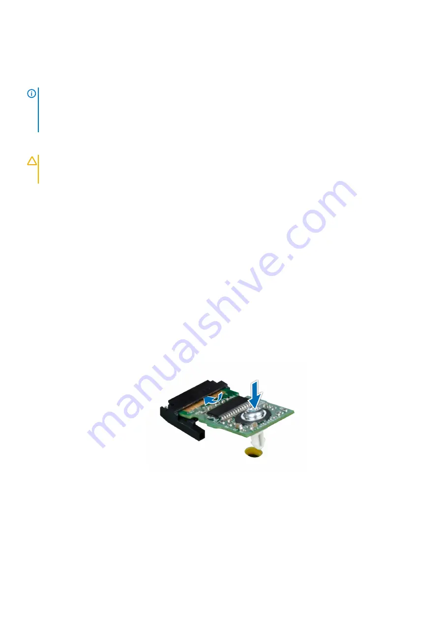
1. To install the TPM, align the edge connectors on the TPM with the slot on the TPM connector.
2. Insert the TPM into the TPM connector such that the plastic rivet aligns with the slot on the system board.
3. Press the plastic rivet until the rivet snaps into place.
4. Replace the screw that secures the TPM to the system board.
Figure 113. Installing the TPM
Next steps
1.
2. Follow the procedure listed in
After working inside your system
3. To verify if the memory module has been installed properly, press F2 and navigate to
System Setup Main Menu > System BIOS >
Memory Settings
. In the
Memory Settings
screen, the System Memory Size must reflect the updated capacity of the installed
memory.
4. If the value is incorrect, one or more of the memory modules may not be installed properly. Ensure that the memory module is firmly
seated in the memory module socket.
Installing and removing system components
145
Содержание PowerEdge R940xa
Страница 15: ...Figure 9 Configuration and layout Figure 10 Express service tag PowerEdge R940xa system overview 15 ...
Страница 17: ...Figure 13 Rear view configuration Figure 14 Jumper settings PowerEdge R940xa system overview 17 ...
Страница 19: ...Figure 18 Electrical overview PowerEdge R940xa system overview 19 ...
Страница 119: ...Figure 86 Installing the X8 PCIe Riser 1 Installing and removing system components 119 ...