


Removing the heat-sink assembly
NOTE:
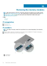
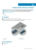
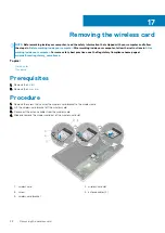
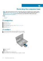
Before working inside your computer, read the safety information that shipped with your computer and follow
the steps in
Before working inside your computer
. After working inside your computer, follow the instructions in
. For more safety best practices, see the Regulatory Compliance home page at
www.dell.com/regulatory_compliance
NOTE:
The heat sink may become hot during normal operation. Allow sufficient time for the heat sink to cool before you
touch it.
CAUTION:
For maximum cooling of the processor, do not touch the heat transfer areas on the heat sink. The oils in your
skin can reduce the heat transfer capability of the thermal grease.
Topics:
•
•
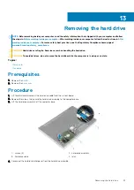
Prerequisites
1. Remove the
.
2. Remove the
3. Remove the
.
4. Follow the procedure from step 1 to step 3 in “
5. Remove the
.
6. Remove the
7. Remove the
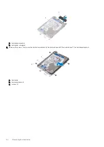
Procedure
NOTE:
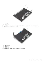
The number of screws and the appearance of the heat-sink assembly may be different on your computer
depending on the configuration ordered.
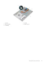
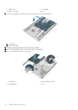
1. Disconnect the fan cable from the system board.
2. In sequential order, as indicated on the heat-sink assembly, loosen the captive screws that secure the heat-sink assembly to the
system board.
3. Remove the screws that secure the heat-sink assembly to the system board.
4. Lift the heat-sink assembly off the system board.
23
36
Removing the heat-sink assembly
Содержание Inspiron 14 5000
Страница 1: ...Inspiron 14 5000 Service Manual Regulatory Model P64G Regulatory Type P64G002 ...
Страница 14: ...1 optical drive bezel 2 optical drive 3 optical drive bracket 4 screws 2 14 Replacing the optical drive ...
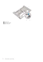
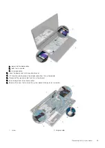
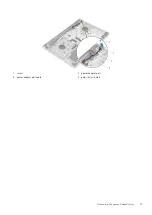
Страница 32: ...a computer base b optical drive interposer c optical drive cable 32 Removing the computer base ...
Страница 40: ...3 latch 4 screw 40 Removing the I O board ...
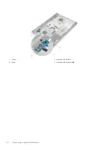
Страница 50: ...1 screw 2 power button board 3 tape 4 power button board cable 50 Removing the power button board ...
Страница 58: ...1 palm rest assembly 58 Removing the palm rest assembly ...
Страница 64: ...1 plastic scribe 2 camera cable 3 camera 4 display back cover 64 Removing the camera ...
Страница 70: ...a screws 12 b display hinges 2 c display back cover 70 Removing the display hinges ...
Страница 73: ...1 display cable 2 display back cover 3 camera cable 4 tape Removing the display cable 73 ...
Страница 76: ...1 display back cover and antenna assembly 76 Removing the display back cover and antenna assembly ...


