background image

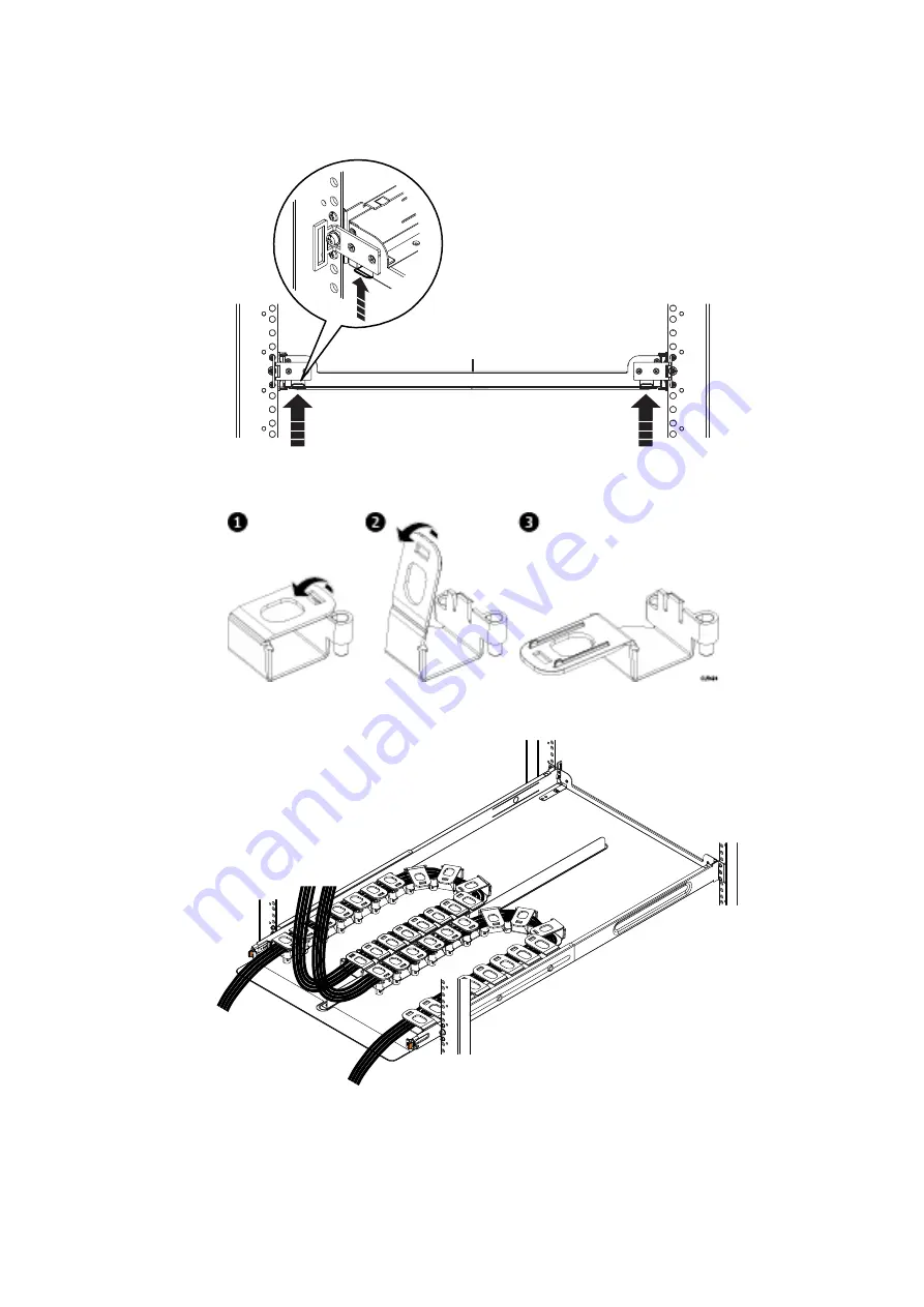
3. Orient the tray so that the UP arrow is pointed up and the end of the tray that is labeled FRONT is to the front of the rack.

Slide the tray into the rails until it locks into place with an audible click. To release the tray, press the spring clips up and pull
the tray towards the front of the rack.

CL5523

Figure 32. Spring clips—push up to release tray

Figure 33. Opening the cable chain lids

4. Unclip and open all lids on the cable chains.

CL5505

Figure 34. Cable positioning in cable chains

5. Refer to the application guide for the shelf you are installing. Using the 1-inch graduations on the back edge of the tray,

route the cables through the cable chains to their suggested lengths, keeping in mind the correct pig-tail lengths. The two

38

Install the Disk Shelves in the Rack

Содержание Data Domain DD9300

Страница 1: ...Dell EMC Data Domain DD9300 System Installation Guide September 2020 Rev 02 ...

Страница 2: ...tial damage to hardware or loss of data and tells you how to avoid the problem WARNING A WARNING indicates a potential for property damage personal injury or death 2020 2020 Dell Inc or its subsidiaries All rights reserved Dell EMC and other trademarks are trademarks of Dell Inc or its subsidiaries Other trademarks may be trademarks of their respective owners ...

Страница 3: ...lves in the Rack 21 Remove filler panels 21 Install an ES30 or FS15 shelf into the rack 21 Racking and cabling 21 Rail kit 22 Installing the rails in the cabinet 22 Adjusting for various rack types 23 Installing the rails using the adapter hardware 23 Installing the shelf on the rails 25 Install a DS60 shelf into the rack 26 Installing rails 27 Installing the shelf onto the rails 30 Inserting and ...

Страница 4: ...les 61 Power on all systems 62 Chapter 5 Configure System for Use 63 Enable administrative communication 63 Accepting the End User License Agreement 64 Run the configuration wizard 64 Configuring the network 64 Configuring additional system parameters 66 Configure HA 67 4 Contents ...

Страница 5: ...ront channel 29 19 Sliding the shelf chassis into the rails 31 20 Unlocking the casters 31 21 Locking the casters 32 22 Removing the straps 32 23 Inserting and securing the shelf to the cabinet shoulder screw configuration 33 24 Removing semi captive screws 34 25 Installing ears to rack using truss head screws 34 26 Installing top cover using truss head screws shelf and rack not shown 34 27 Remova...

Страница 6: ...nd alignment pins 46 48 Nutbar installation Left nutbar shown 47 49 DD9300 with ES30 shelves single node DD Cloud Tier or ER 51 50 DD9300 with ES30 shelves HA or HA with DD Cloud Tier 53 51 DD9300 with DS60 shelves 55 52 DD9300 with DS60 shelves HA 57 53 DD9300 with DS60 shelves DD Cloud Tier or HA and DD Cloud Tier 59 54 DD9300 with DS60 shelves ERSO 60 55 HA interconnect 61 6 Figures ...

Страница 7: ...instructions 51 10 DD9300 with ES30 standby node cabling instructions 52 11 DD9300 with DS60 cabling instructions 54 12 DD9300 with DS60 primary node cabling instructions 55 13 DD9300 with DS60 standby node cabling instructions 56 14 DD9300 with DS60 DD Cloud Tier or HA and DD Cloud Tier primary node cabling instructions 57 15 DD9300 with DS60 DHA and DD Cloud Tier standby node cabling instruction...

Страница 8: ...Follow the instructions in Configure System for Use on page 63 to configure factory racked systems The following documents available from the Online Support website provide additional information about factory racked systems Dell EMC 40U P Cabinet Site Preparation Guide Dell EMC 40U P Cabinet Unpacking and Setup Guide Dell EMC Titan S Site Preparation Guide Dell EMC Titan S Unpacking and Setup Gui...

Страница 9: ... disconnect power from the system Ensure that the socket outlets are located near the equipment and are easily accessible Permanently unplug the unit if you think it is damaged in any way and before moving the system Systems include two power supplies To remove system power completely disconnect both power supplies The power connections must always be disconnected before removal or replacement of ...

Страница 10: ...uirements For installations in racks that are 28U 49 inches or less above the floor use the lower mast which is rated for 400 pounds For installations in racks that are more than 28U 49 inches above the floor use the lower mast configuration and a support table with the Voyager conversion kit which is rated for 225 pounds Adjusting the arms for a frontal lift About this task If you plan to use the...

Страница 11: ... task If you are using the Alum A Lift to install or remove components above 49 inches 28U from the floor use the single lower mast configuration with the Voyager conversion kit and support table Steps 1 Unpack the Voyager kit 2 Use the instructions provided within the kit to reconfigure the lift Introduction and Preparation 11 ...

Страница 12: ...CL5422 1 2 Figure 3 Reconfiguring the portable lift with the Voyager conversion kit 12 Introduction and Preparation ...

Страница 13: ...t is universal in that it supports all rack mounting hole types and sizes Both the front and the rear ends of the rail kit contain threaded posts that come with a cap installed The cap fits square and round hole unthreaded racks Large flat headed M4 screws insert through the rail into the rail kit to secure the rail to the rack When installing rails do not tighten the screws all the way until all ...

Страница 14: ... an HA pair is U22 U23 in rack 1 The designated location for the standby node of an HA pair is U25 26 in rack 1 NOTE The designated slots in the rack are the recommended location for the systems to support the cabling described in this document Other locations may require different cable lengths for some configurations Install the rails This procedures describes how to install the mounting rails S...

Страница 15: ...the rear of the rails 4 At the rear of the cabinet align and insert the two adaptors on the rear of the rail with the mounting holes in the NEMA channel Make sure the rail is level 5 Use an 18 inch screwdriver minimum to secure the rear of the rail to the NEMA channel using one screw 6 Tighten the front screw 7 Repeat for the other rail Install the system into a rack About this task CAUTION Data D...

Страница 16: ...NT label which is in a slot just beneath the power supply on the rear of the chassis is not damaged or snagged during the installation of the system into the rack Steps 1 From the front of the rack lift the chassis to install the system in the rack in the correct location 2 Slide the unit onto the rails and push it fully into the cabinet until the mounting holes on the unit are flush with the NEMA...

Страница 17: ...Install the System in the Rack 17 ...

Страница 18: ...SNT label in the slot just beneath the power supply at the rear of the chassis Figure 7 Service tag components removed for clarity 1 Service tag bracket 2 Locking tab 3 Service tag 18 Install the System in the Rack ...

Страница 19: ... mounting hole of the rail Figure 8 Installing the CMA on the rack 3 Open the velcro straps to route cables through the CMA Secure the cables in place using the velcro straps 4 To adjust the CMA position depth in or out pull inward on the orange latches 1 and pull out or push in on the arm simultaneously as needed 2 NOTE The I O modules the NVRAM module the power supply units and the 2 5 disks can...

Страница 20: ...s to string N and the M is the number of the shelf in the string For example V3 2 refers to the second shelf in the third string 3 Secure each expansion shelf in the rack 4 When installing an SSD shelf for Data Domain metadata on flash The SSD shelf counts towards the total number of shelves connected to the system Data Domain recommends installing the SSD shelf in the V1 1 positon but if that is ...

Страница 21: ...SD shelf Racking and cabling EMC has adopted recommended racking guidelines To provide the best trade off in terms of serviceability system expansion and cabling mount the controller starting above the first set of shelves in the rack usually 13U for most systems You can connect the 2 meter cable attached to the controller to any shelf in the same rack Install filler panels in unused rack openings...

Страница 22: ...nt Install each rail in the cabinet Steps 1 From the front of the cabinet insert the rail alignment pins above and below the bottom U mark on the rear cabinet channel Alignment pins here EMC2892b 3U Rear channels Figure 10 Holes for alignment pins 2 Pull the sliding rail to the front of the cabinet and secure it to the front channel at the middle two holes of the rail using two of the provided scr...

Страница 23: ...32 or 12 24 The front edge of each rail is stamped L or R for left and right sides when facing the front of the rack Since the brackets cover these markings make a note as to which rack is L and which rack is R Use a 2 Phillips screwdriver with a shank diameter less than 7 0 mm and the wrench that was included in the kit to tighten the nuts CAUTION The adapter kit is only for static applications w...

Страница 24: ...acket aligned with the rear of the rack b Pull the front of the rail until it is aligned with the inside of the rack front c Attach the front of the rail bracket assembly to the front of the rack For M6 or 12 24 tapped rack holes insert M5 screws through the rack hole positions as shown in Attaching the rail to the rack on page 25 Secure the screws using the furnished nuts For M5 or 10 32 tapped r...

Страница 25: ...nclosure is heavy and should be installed into or removed from a rack by two people To avoid personal injury and or damage to the equipment do not attempt to lift and install the enclosure into a rack without a mechanical lift and or help from another person Steps 1 With help from another person lift the enclosure and from the front of the cabinet rack slide the enclosure onto the rails Sliding th...

Страница 26: ... enclosure 2 Once the enclosure is completely seated into the rear tabs secure the enclosure tighten the screws two on each rail that secure the rails to the channels 3 Secure the front of the enclosure to the front vertical channels with four screws two per side but do not tighten the screws until they are all in place Securing the front of the enclosure on page 26 Rear Front Screw 2 Screw 2 CL47...

Страница 27: ...the two M5 adapters from the adapter mounting block on the rails b Select the required adapters from the hardware kit and install the adapters into the adapter mounting block The following table shows the pins for third party racks Table 2 Pins for third party racks Rail Pins from kit Part Number and Description Suggested Use 036 028 018 Custom screw M4 x 10MM Quantity 4 per kit Used for any third...

Страница 28: ...two U spaces of the 4U space b With the release latch on the outer rear part of the rear channel place the catch mechanism over the channel c Push the rail back to secure the rail adapters in the cabinet channel An audible click indicates that the rail is secure in the channel d Make sure the rear post catch mechanism is secure and attached 28 Install the Disk Shelves in the Rack ...

Страница 29: ...n is secure Front Right CL4866 Figure 18 Installing the right rail to the front channel 6 Install the left rail by repeating step 3 or step 4 7 On both left and right rail assemblies install a single long screw between the rail posts in the upper screw hole to secure the rails as follows a For Dell EMC racks or racks that do not have threaded holes insert a single M5 screw into the larger of the t...

Страница 30: ...eople to install About this task CAUTION Secure the enclosure to the portable lift using the securing straps before moving the lift Steps 1 If a portable lift is not available or cannot access the rack you must remove the components from the shelf before it is installed on the rails a Refer to the procedures for removing the Power Supplies link control cards LCCs and Fan Modules and remove each FR...

Страница 31: ...casters by lifting the locking tabs as shown in the following figure and carefully slide the shelf into the cabinet as far as the lift allows CL5424 Figure 20 Unlocking the casters 5 Lock all four casters by pressing down on the locking tab as shown in the following figure so the lift does not roll as the shelf is pushed into the cabinet Install the Disk Shelves in the Rack 31 ...

Страница 32: ...ecured within the cabinet 8 If the shelf was depopulated before installation repopulate the shelf as follows a Reinstall the disk drives in the exact location from which they were removed b Reinstall the Fan modules c Slide the shelf into the cabinet d From the rear of the cabinet reinstall the power supplies and the link control cards LCCs into the shelf Inserting and securing the top cover and s...

Страница 33: ...lips with patch Can be used in non Dell EMC racks Steps 1 For Dell EMC racks use the orange shelf latch handles to push the shelf completely into the cabinet Align the two semi captive M5 shoulder screws on each side with the mounting holes on the cabinet Thread the shoulder screws into the mounting holes and finger tighten the shoulder screws Figure 23 Inserting and securing the shelf to the cabi...

Страница 34: ... cabinet To secure a top cover that does not have any mounting hardware use the screws or pins from the kit that accompanies the device These screws secure the shelf cover and prevent the cover from coming out of the cabinet during operation Secure the top cover to the rack as follows a If the shelf is being installed into a Dell EMC rack secure the top cover to the rack using M5 truss head screws...

Страница 35: ...to install the 1U cable management tray Racks and rails You can secure the 1U cable tray to Dell EMC and non Dell EMC racks that use a sliding rail system The rail kits are included in the cable tray packaging and are compatible with racks with the following types of holes 3 8 inch square holes 9 32 inch round holes 10 32 12 24 M5X 8 or M6X1 pre threaded holes The following table shows the hardwar...

Страница 36: ...Figure 28 Blue tab on rail must be pushed in About this task NOTE This procedure describes the installation of the 1U cable management tray into a standard Dell EMC rack For third party racks use the additional hardware that comes with the 1U cable management arm to install the rails as necessary The rails come preassembled with adapters that fit into standard round mounting holes If the rack has ...

Страница 37: ... fit the rack you are using Insert the two adapters on the rail into the mounting holes in both the front and the rear of the rails Secure the rails to the rack using two knurled screws from the hardware package one in the front of the rail and one in the rear of the rail Torque the screws to 12 16 inch pounds Repeat for the other rail Figure 31 Installing tray Install the Disk Shelves in the Rack...

Страница 38: ...of the rack CL5523 Figure 32 Spring clips push up to release tray Figure 33 Opening the cable chain lids 4 Unclip and open all lids on the cable chains CL5505 Figure 34 Cable positioning in cable chains 5 Refer to the application guide for the shelf you are installing Using the 1 inch graduations on the back edge of the tray route the cables through the cable chains to their suggested lengths keep...

Страница 39: ...hains so the lids are facing up and the hinges are all facing each other Arrange the two cable chains so that they form a U shape Figure 36 Attaching cable chains to tray 7 Attach the Cable Chains to the tray by attaching the clips onto the tabs on the rear of the tray CL5500 Figure 37 Installing the chassis bracket into the shelf 8 Snap the chassis bracket clips into the brackets on the side of t...

Страница 40: ...ation guide and connect the cables as required Dress the cable runs with proper cable strain reliefs when routing to the rack Disconnecting cables for a shelf installed with the 1U cable management tray When servicing a shelf installed with the 1U cable management tray cables might need to be disconnected to perform servicing procedures Steps 1 Unplug disconnect all cables from the rear of the she...

Страница 41: ...ls and components in the customer racks Discard all silver screws removed from the shipping rack Modifying rail lengths This procedure details how to extend or shorten the rail lengths to accommodate third party racks About this task The rails have four adjustment ranges 18 22 22 26 default 26 30 30 34 The length adjustments provided in this procedure use the default length of 22 26 as a baseline ...

Страница 42: ... remove the forward most screw and nut 4 Slide the length adjustment bracket to the rear of the rail until it stops CL5502 Figure 42 26 30 Marking 5 Slide the inner rail mechanism to the rear of the rail until the 26 30 mark is visible If the inner mechanism is locked depress the leaf spring to free it 6 Adjust the hardware to make sure the mounting holes are aligned with the mounting slots 7 Secu...

Страница 43: ... the third party rack About this task CAUTION Exercise care when installing the short rails Exposed metal edges may be sharp and could damage cabling or cause injury to personnel Refer to the following tables and figures to install each shelf The following table shows the rail pins and their suggested use Table 4 Pins for third party racks Rail Pins from kit Part Number and Description Suggested U...

Страница 44: ...l location in 4U space n a n a 2 Universal Rail Pins see previous table for details n a Part of PN 106 569 300 and 106 529 209 3 Shelf rails 2 each kit for each node 2 PN 106 569 300 and 106 529 209 Figure 44 Rail installation 44 Install the Disk Shelves in the Rack ...

Страница 45: ...channel An audible click indicates that the rail is secure in the channel Make sure the rear post catch mechanism is secure and attached 4 Install the right rail to the front channel a Align the front of the right rail so that it is level and the front rail pins are aligned with the middle holes of the bottom two U spaces of the 4U space b Pull the rail forward with the posts aligned with the midd...

Страница 46: ...front and rear of the rack The following table lists the parts that are referenced in Location of securing screws and alignment pins on page 46 Table 6 Parts list Image Description Qty Part number 1 Node rail location in 4U space n a n a 2 Node rail square alignment pins n a Part of PN 100 569 209 4 M5 or M4 securing screws 4 PN 106 002 452 or 036 028 018 CL5552 4U space Front view 4 2 2 1 4 2 2 1...

Страница 47: ...e 4U space n a N A 3 Rail bracket alignment pins n a N A 4 Nutbar alignment pins n a Part of PN 051 000 357 and PN 051 000 356 5 Nutbar M5 securing screws black 4 PN 036 709 013 Figure 48 Nutbar installation Left nutbar shown NOTE The nutbars are not interchangeable There is a distinct nutbar for the left and right side Use part numbers for identification Install the Disk Shelves in the Rack 47 ...

Страница 48: ...ar 051 000 357 directly above the rail assembly 2 Secure the nutbar with two M5 securing screws one above the top alignment pin and one below the lower alignment pin 3 Repeat the previous steps for the right nutbar 051 000 356 48 Install the Disk Shelves in the Rack ...

Страница 49: ...t Cables and Power On Topics Connecting ES30 shelves Connecting DS60 shelves Connecting the HA interconnect Installing the front bezel Connect data cables Power on all systems 4 Connect Cables and Power On 49 ...

Страница 50: ...es to connect to ES30 shelves The primary node uses cables for ES30 host ports and the standby node uses cables for ES30 expansion ports DD9300 single node DD Cloud Tier or ERSO DD9300 systems support a maximum of 28 shelves divided into four sets of seven shelves NOTE For configurations of 16 SAS shelves or less do not exceed four shelves per set Table 8 DD9300 with ES30 cabling instructions Stri...

Страница 51: ... For configurations of 16 SAS shelves or less do not exceed four shelves per set Table 9 DD9300 with ES30 primary node cabling instructions String Loop I O Port Shelf Port Length a 1 I O 7 Port 0 B controller HOST port of shelf V1 1 2M 1 I O 2 Port 0 A controller HOST port of the highest number shelf in V1 2M 2 I O 7 Port 2 B controller HOST port of shelf V2 1 2M Connect Cables and Power On 51 ...

Страница 52: ...S30 standby node cabling instructions String Loop I O Port Shelf Port Length a 1 I O 7 Port 0 A controller EXPANSION port of shelf V1 1 2M 1 I O 2 Port 0 B controller EXPANSION port of the highest number shelf in V1 2M 2 I O 7 Port 2 A controller EXPANSION port of shelf V2 1 2M 2 I O 2 Port 2 B controller EXPANSION port of the highest number shelf in V2 2M 3 I O 7 Port 1 A controller EXPANSION por...

Страница 53: ...Figure 50 DD9300 with ES30 shelves HA or HA with DD Cloud Tier Connect Cables and Power On 53 ...

Страница 54: ... 1 is recommended for better performance because this will the 1st hop where data will be written If the SSD shelf is connected to the last enclosure in a chain then each read write request has to go through many hops which introduces latency issues when compared to when the SSD shelf is on the 1st shelf of a chain 5 Use the cable management assembly to support and organize all cables DD9300 Table...

Страница 55: ...th HA Table 12 DD9300 with DS60 primary node cabling instructions String Loop I O Port Shelf Port Length a 1 I O 7 Port 0 A controller port 0 of shelf V1 1 2M 1 I O 2 Port 0 B controller port 0 of the highest number shelf in V1 2M Connect Cables and Power On 55 ...

Страница 56: ...es up to 5M can be used Table 13 DD9300 with DS60 standby node cabling instructions String Loop I O Port Shelf Port Length a 1 I O 7 Port 0 B controller port 2 of shelf V1 1 2M 1 I O 2 Port 0 A controller port 2 of the highest number shelf in V1 2M 2 I O 7 Port 1 B controller port 2 of shelf V2 1 2M 2 I O 2 Port 1 A controller port 2 of the highest number shelf in V2 2M 3 I O 7 Port 2 B controller...

Страница 57: ... Cloud Tier or HA and DD Cloud Tier primary node cabling instructions String Loop I O Port Shelf Port Length a 1 I O 7 Port 0 A controller port 0 of shelf V1 1 2M 1 I O 2 Port 0 B controller port 0 of the highest number shelf in V1 2M 2 I O 7 Port 1 A controller port 0 of shelf V2 1 2M Connect Cables and Power On 57 ...

Страница 58: ... used Table 15 DD9300 with DS60 DHA and DD Cloud Tier standby node cabling instructions String Loop I O Port Shelf Port Length a 1 I O 7 Port 0 B controller port 2 of shelf V1 1 2M 1 I O 2 Port 0 A controller port 2 of the highest number shelf in V1 2M 2 I O 7 Port 1 B controller port 2 of shelf V2 1 2M 2 I O 2 Port 1 A controller port 2 of the highest number shelf in V2 2M 3 I O 7 Port 2 B contro...

Страница 59: ...h ERSO Table 16 DD9300 with DS60 ERSO String Loop I O Port Shelf Port Length a 1 I O 7 Port 0 A controller port 0 of shelf V1 1 2M 1 I O 2 Port 0 B controller port 0 of the highest number shelf in V1 2M 2 I O 7 Port 1 A controller port 0 of shelf V2 1 2M Connect Cables and Power On 59 ...

Страница 60: ... port 0 of shelf V3 1 2M 3 I O 2 Port 2 B controller port 0 of the highest number shelf in V3 5M 4 I O 7 Port 3 A controller port 0 of shelf V4 1 5M 4 I O 2 Port 3 B controller port 0 of the highest number shelf in V4 5M a Cable lengths shown are designed for Data Domain racks Longer cables up to 5M can be used Figure 54 DD9300 with DS60 shelves ERSO 60 Connect Cables and Power On ...

Страница 61: ...ort 1 of the interconnect I O module in node 1 slot 1 Installing the front bezel Steps 1 Align the bezel with the enclosure 2 Gently push the bezel into place on the cabinet until it latches 3 If the bezel has a key lock lock the bezel the provided key Connect data cables 1 Enable data transfer Ethernet connectivity Repeat for each connection a If using 1 Gb copper Ethernet attach a Cat 5e or Cat ...

Страница 62: ...helves are powered on before powering on the controller 3 Provide power to power on the controller The system powers on when plugged in The first boot may take several minutes to complete NOTE Connect systems to redundant AC power sources Redundant power sources allow one AC source to fail or be serviced without impacting system operation PSU0 should be attached to one AC source PSU1 should be att...

Страница 63: ...he prompt on your terminal to log in then complete Step 4 4 Verify the front blue power LED blue square is on If it is not make sure the power cables are fully seated at both ends and both AC sources are on 5 NOTE The initial username is sysadmin and the initial password is the system serial number Log in to the Data Domain console using the sysadmin username localhost localdomain login sysadmin 6...

Страница 64: ...ation wizard manually by typing config setup After you complete the basic configuration with a wizard you can use additional configuration controls in DD System Manager and the CLI to further configure the system DD System Manager configuration wizard DD System Manager provides a single consolidated management interface that allows for configuration and monitoring of many system features and syste...

Страница 65: ...eway IP address 8 Enter up to three DNS servers to use for resolving host names to IP addresses Use a comma separated or space separated list Enter a space for no DNS servers Or accept the IP addresses of the DNS servers if the system was able to discover them DNS Servers Enter the DNS Server list zero one two or three IP addresses 192 168 10 1 9 A summary of the network settings is displayed You ...

Страница 66: ...ter config set location Dallas Regional Data Center Lab 5000 Apple Drive Suite 130 Dallas Tx The System Location is Dallas Regional Data Center Lab 5000 Apple Drive Suite 130 Dallas Tx 3 To add one or more time servers enter ntp add timeserver 192 168 101 1 Remote Time Servers 192 168 10 1 4 To enable the NTP daemon enter ntp enable NTP enabled 5 To change the system time zone enter config set tim...

Страница 67: ... 11 28 2022 dd ha3a example com ca trusted ca Tue Aug 8 21 04 53 2018 Mon Aug 7 21 04 53 2024 2 Verify the certificate subject name on the standby node Run the following command adminaccess certficate show sysadmin dd ha3b adminaccess certificate show Subject Type Application Valid From Valid Until dd ha3b example com host https Tue Aug 8 15 11 28 2018 Sat Aug 7 22 11 28 2022 dd ha3b example com c...

Страница 68: ...tware version 8 Check the system for alerts Run the following command alerts show current If the system displays System is misconfigured the SSDs were not removed from the front of the primary node Run the enclosure show misconfiguration command to get more details 9 Verify the HA status Run the following command ha status HA System Name dd ha3a emc com HA System Status highly available Node Name ...

Отзывы: