6.
On the motherboard, locate the 10-Pin USB header.
The location of this header will vary between different
motherboard brands. Connect Pin 1 of the ribbon
cable to Pin 1 of the USB header. Please verify pin-
out before turning on your system.
Figure 2
Figure 1
7.
Turn the system on and watch the reader carefully, ensuring that the LEDs light up.
Note: The header marked J10 is an optional auxilliary port to which an additional USB
socket can be hooked up.
Figure 3
3.5” bay
2.
Click
eFilm Reader-19
from the list of
products on the left to open the installation
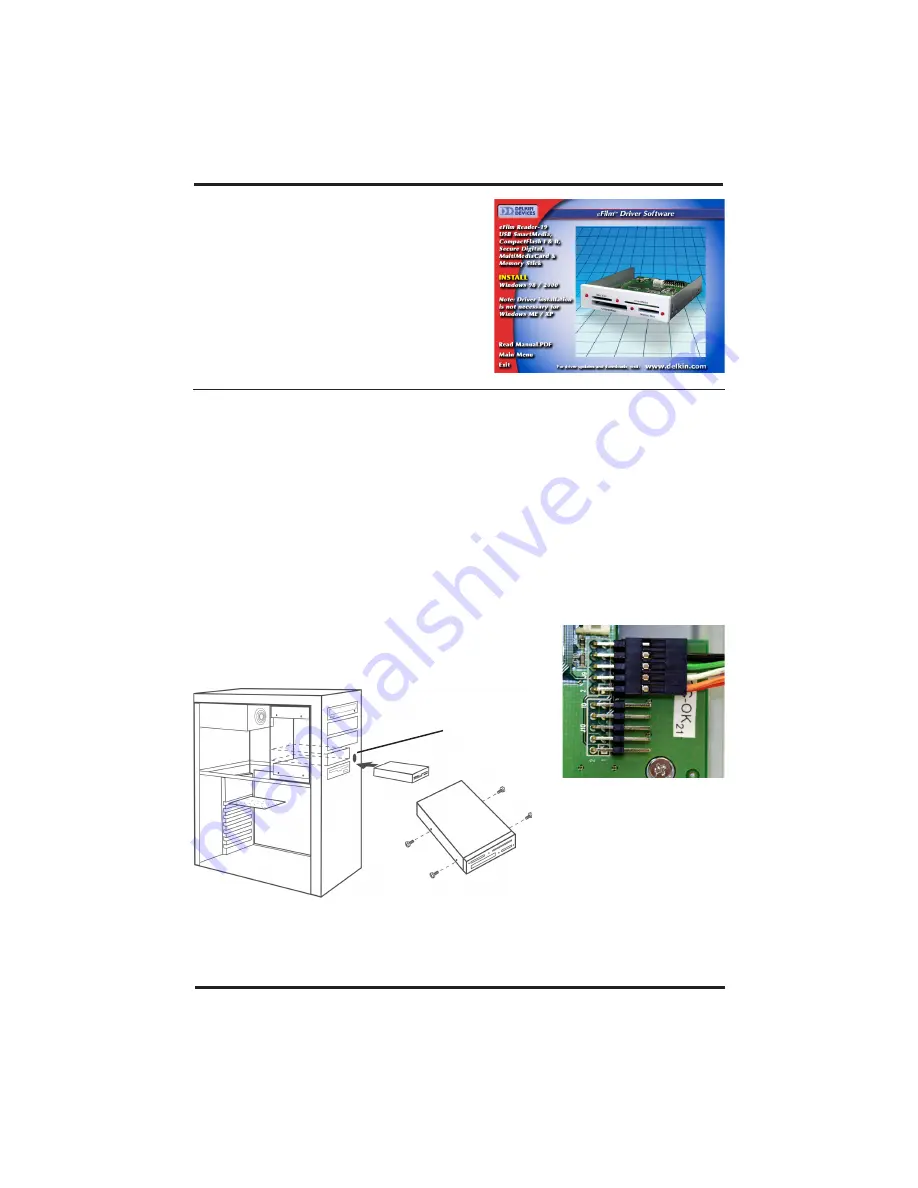
window for the Reader-19. (See Figure 1)
3.
Click the
Install
button and follow the on-
screen instructions. For best results, allow
the drivers to be installed into the default
locations.
4.
When prompted, reboot the computer to
complete installation.
Hardware Installation
Installing the eFilm Reader-19 will require opening your PC and configuring your
hardware. Refer to your computer’s manual for disassembly/assembly instructions.
1.
Shut your system down and turn off the power.
2.
Disconnect the power cord and remove the cover from your computer. Touch a bare
-metal part of your computer to discharge static electricity.
3.
Remove the faceplate of an available 3.5” drive bay.
4.
Slide the Reader-19 into the bay and secure it with screws. (See Figure 2)
5.
On the reader, locate pin 1 on the 10-pin header marked J9 and connect Pin 1 of the
ribbon cable to it. The wire colored red or textured differently from the others will
identify Pin 1 of the ribbon cable. (See Figures 3)
USB CF / SM / SD / MMC / MS Reader/Writer
DDREADER-19
Page 2
Delkin Devices User’s Manual


