background image

6000XL Series Service and Installation Manual

11

For customer service, call (800) 733-8829, (800) 733-8821, Fax (888) 779-2040, www.delfield.com

Delfield

®

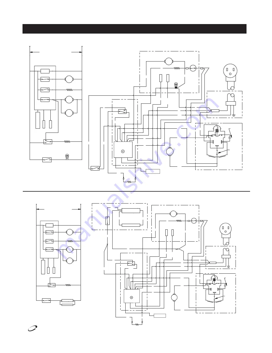
WIRINg DIAgRAMS: FREEzERS

LINE VOLTAGE 

115/60/1 

SEE NAMEPLATE FOR MAXIMUM 

FUSE SIZE 

COMPRESSOR 

TEMPERATURE 

CONTROL 

SENSOR 

(IF USED) 

LED DISPL

AY 

EV

AP C

OIL 

CABINET AIR  SENSOR 

L1 

3) UNIT SHOWN WITH COMPRESSOR  

BOX 

CONTROL 

HEATER 

DOOR FRAME 

ENERGY SAVER 

 SWITCH 

RUNNING AND DOORS CLOSED 

2) THIS UNIT MUST BE GROUNDED 

1) USE COPPER CONDUCTORS ONLY 

ENERGY SAVER 

GREY 

 SWITCH 

DOOR 

BLK 

HINGE 

DOOR 

RED  

1.1,2,3 2.1,2,3 3.1,2,3 

CONTROL 

TEMPERATURE 

BLK 

(IF USED) 

LED DISPLAY 

 SWITCH 

START 

WINDING 

14 

10 

FAN 

CONDENSER 

BLK 

WINDING 

RUN 

STRIPES 

WITH BLUE  

EVAPORATOR HOUSING 

MOTOR 

EVAP FAN 

SENSOR 

CABINET AIR 

EV

AP C

OIL 

SENSOR 

LIGHT 

INCANDESCENT 

BLK 

BLK 

11 

START  
CAPACITOR 

POWER BOX 

SPLICE 

NUT 

WIRE 

PLUG 

COMPRESSOR 

BLK 

FRAME HEATERS 

NOTES: 

CONTROL 

CIRCUIT 

RELAY 

COMPRESSOR 

LIGHT 

INCANDESCENT 

1.1,2,3 2.1,2,3 3.1,2,3 

HIGH TEMP 

LIMIT 

SWITCH 

HEATER 

DEFROST  

BLUE 

SWITCH 

WINDING 

PROTECTOR 

12 

13 

FAN RELAY 

HEATER RELAY 

EVAPORATOR FAN 

DEFROST HEATER 

CONDENSOR FAN 

LED DISPLAY 

CONDENSOR FAN 

DEFROST HEATER 

EVAPORATOR FAN 

DOOR FRAME 

LINE VOLTAGE 

115/60/1 

SEE NAMEPLATE FOR MAXIMUM 

FUSE SIZE 

ENERGY SAVER 

 SWITCH 

HEATER RELAY 

1.1,2,3 2.1,2,3 3.1,2,3 

COMPRESSOR 

RELAY 

CONTROL 

TEMPERATURE 

LED DISPL

AY 

(IF USED) 

EV

AP C

OIL 

SENSOR 

SENSOR 

CABINET AIR 

FAN RELAY 

CIRCUIT 

CONTROL 

L1 

HEATER 

FRAME HEATERS 

TEMPERATURE 

CONTROL 

1.1,2,3 2.1,2,3 3.1,2,3 

BLK 

1  2 

C  L 

H  N 

(IF USED) 

1) USE COPPER CONDUCTORS ONLY 

2) THIS UNIT MUST BE GROUNDED 

RUNNING AND DOORS CLOSED 

3) UNIT SHOWN WITH COMPRESSOR  

COMPRESSOR 

CONTROL 
BOX 

NOTES: 

SWITCH 

ENERGY SAVER 

BLUE 

CABINET AIR 

BLK 

BLK 

CONDENSER 

FAN 

COMPRESSOR 

RUN 

WINDING 

14 

12 

WINDING 

START 

13 

PROTECTOR 

WINDING 

EVAP FAN 

DEFROST  

BLK 

BLK 

WITH BLUE  

STRIPES 

MOTOR 

EV

AP C

OIL 

SENSOR 

SENSOR 

HEATER 

SWITCH 

LIMIT 

HIGH TEMP 

EVAPORATOR HOUSING 

POWER BOX 

SPLICE 

10 

11 

WIRE 

NUT 

CAPACITOR 

START  

PLUG 

SWITCH 

FLUORESCENT 

LAMP  

FLUORESCENT LAMP ASSEMBLY 

FLUORESCENT LIGHT 

FLUORESCENT LAMP  

BLK 

RED 

BALLAST 

BLUE 

LAMP SWITCH 

FLUORESCENT 

LAMP BALLAST 

FLUORESCENT 

LAMP  

FLUORESCENT 

BLK 

BLK 

GREY 

6125XL-S, 6125XL-SH

6125XL-G, 6125XL-GH

Содержание 6125XL-S

Страница 1: ...are Manual Please read this manual completely before attempting to install or operate this equipment Notify carrier of damage Inspect all components immediately See page 2 Refrigerators and Freezers Effective Date December 2007 IMPORTANT INFORMATION READ BEFORE USE PLEASE SAVE THESE INSTRUCTIONS Delfield ...

Страница 2: ...tents Serial Number Information Even though most equipment is shipped crated care should be taken during unloading so the equipment is not damaged while being moved into the building 1 Visually inspect the exterior of the package and skid or container Any damage should be noted and reported to the delivering carrier immediately 2 If damaged open and inspect the contents with the carrier 3 In the e...

Страница 3: ... 5 33 2 1923 20 F 12 5 454 5 15p 6076XL SH S G GH 115 16 0 66 5 48 3 2092 2488 20 F 12 5 12 5 622 5 20p 6176XL S SH 115 208 230 15 0 66 5 48 3 1516 1923 20 F 12 5 12 5 622 14 20P MODEL VOLTAGE AMPS STORAGE CAPACITY FT3 SHELF CAPACITY FT2 REQUIRED BTU HR EVAP TEMP R 404A CHARGE OZ SHIPPING WEIGHT NEMA PLUG TYPE 6025XLR SH S G GH 110 2 0 20 15 1 2092 20 F 12 5 274 5 15p 6125XLR S SH 110 2 0 20 15 1 ...

Страница 4: ...k into the hinge 9 Reinstall the plastic screw covers removed in step 2 10 Reinstall the door by reversing step 1 Installation Location Units represented in this manual are intended for indoor use only Be sure the location chosen has a floor strong enough to support the total weight of the cabinet and contents A fully loaded 6000XL series can weigh as much as 1500 pounds Reinforce the floor as nec...

Страница 5: ...the thermostat knob The switch controls power to the frame heater to minimize condensation around the door opening Press the switch to the 0 position to conserve energy If excessive condensation is observed on the door opening press the switch to the position red portion of the rocker will be visible Refrigeration Defrost Cycle Refrigerator Whenever the refrigerator is plugged in and the control h...

Страница 6: ...ance the condenser fins must be cleaned of dust dirt and grease regularly It is recommended that this be done at least every three months If conditions are such that the condenser is totally blocked in three months the frequency of cleaning should be increased Clean the condenser with a vacuum cleaner or stiff brush If extremely dirty a commercially available condenser cleaner may be required Stai...

Страница 7: ...become loose If it is noticed that the door is beginning to sag it may become necessary to tighten the screws that mount the hinge brackets to the frame of the unit If the doors are loose or sagging this can cause the hinge to pull out of the frame which may damage both the doors and the door hinges In some cases this can require qualified service agents or maintenance personnel Drain Maintenance ...

Страница 8: ...COMPRESSOR BLK FRAME HEATERS NOTES 1 CONTROL CIRCUIT 5 3 RELAY COMPRESSOR LIGHT INCANDESCENT 1 1 2 3 2 1 2 3 3 1 2 3 BOX CONTROL ENERGY SAVER BLK BLUE 1 1 2 3 2 1 2 3 3 1 2 3 CONTROL TEMPERATURE 4 H BLK 2 L C 1 3 L W 5 N 6 F IF USED LED DISPLAY M START WINDING 14 10 FAN CONDENSER BLK W IN D IN G R U N 12 EVAPORATOR HOUSING MOTOR EVAP FAN SENSOR CABINET AIR EVAP COIL SENSOR M W BLK BLK W W W 11 STA...

Страница 9: ...RESSOR LIGHT INCANDESCENT 1 1 2 3 2 1 2 3 3 1 2 3 BOX CONTROL ENERGY SAVER BLK BLUE 1 1 2 3 2 1 2 3 3 1 2 3 CONTROL TEMPERATURE 4 H BLK 2 L C 1 3 L W 5 N 6 F IF USED LED DISPLAY M STAR WINDING 14 10 FAN CONDENSER BLK W IN D IN G R U N 12 EVAPORATOR HOUSING MOTOR EVAP FAN SENSOR CABINET AIR EVAP COIL SENSOR M W BLK BLK W W W 11 START GROUND MOTOR PROTECTOR COMPRESSOR 13 CAPACITOR CONTROL BOX START ...

Страница 10: ...4125 GROUND R U N W IN D IN G TEMPERATURE DOOR FRAME FLUORESCENT LAMP BALLAST FLUORESCENT FLUORESCENT FLUORESCENT LAMP SWITCHES SWITCH ENERGY SAVER FAN MOTOR EVAPORATOR M LAMP LAMP HEATERS FRAME HEATERS BLK W 1 1 2 3 2 1 2 3 3 1 2 3 CONTROL MOTOR PROTECTOR BLK LED DISPLAY IF USED M FAN CONDENSER COMPRESSOR 14 FLUORESCENT LAMP ASSEMBLY LAMP BALLAST FLUORESCENT DOOR FRAME FLUORESCENT RELAY COMPRESSO...

Страница 11: ...CH W W WINDING PROTECTOR 12 13 FAN RELAY F 6 M HEATER RELAY H 4 EVAPORATOR FAN DEFROST HEATER C 1 CONDENSOR FAN M LED DISPLAY CONDENSOR FAN DEFROST HEATER EVAPORATOR FAN DOOR FRAME LINEVOLTAGE 115 60 1 SEE NAMEPLATE FOR MAXIMUM FUSE SIZE ENERGY SAVER SWITCH HEATER RELAY 1 1 2 3 2 1 2 3 3 1 2 3 COMPRESSOR RELAY CONTROL TEMPERATURE LED DISPLAY IF USED 3 L EVAP COIL SENSOR SENSOR CABINET AIR 1 C FAN ...

Страница 12: ...HES DOOR BLK HINGE DOOR RED 1 1 2 3 2 1 2 3 3 1 2 3 CONTROL TEMPERATURE 4 H BLK 2 L C 1 3 L W 5 N 6 F IF USED LED DISPLAY SWITCHES STRIPES WITH BLUE EVAPORATOR HOUSING MOTOR EVAP FAN SENSOR CABINET AIR W W EVAP COIL SENSOR M LIGHT INCANDESCENT W BLK BLK W W W POWER BOX SPLICE NUT WIRE PLUG DOOR FRAME HEATERS NOTES CONTROL CIRCUIT 5 3 RELAY COMPRESSOR LIGHT INCANDESCENT 1 1 2 3 2 1 2 3 3 1 2 3 P HI...

Страница 13: ... Series Service and Installation Manual 13 For customer service call 800 733 8829 800 733 8821 Fax 888 779 2040 www delfield com Delfield Refrigeration Package parts diagram 7 5 6 1 9 4 14 11 12 18 15 17 16 3 ...

Страница 14: ...752 Door lock 3978018 Shelves 2194791 Cable 2194792 Display Freezer One section Item Number Part Number 50Hz Part Description 2 kit 2194783KT 2194964KT Control ETC1 Kit 3 2190152 Switch energy saver 4 2184181 Cord power 5 2162715 2162719 Motor fan evaporator 6 3516274 Fan blade evaporator 1 3516436 Coil evaporator 7 3516429 Valve refrigerant TXV 8 3516205 Clip TXV bulb mounting 19 2194785 2194967 ...

Страница 15: ...Two section Item Number Part Number 50Hz Part Description 2 kit 2194783KT 2194964 Control ETC1 Kit 3 2190152 Switch energy saver 4 2184181 Cord power 5 2162715 2192719 Motor fan evaporator 6 3516274 Fan blade evaporator 1 3516436 Coil evaporator 7 3516429 Valve refrigerant TXV 8 3516205 Clip TXV bulb mounting 19 2194785 2194967 Heater defrost 20 9321629 Clip defrost heater mounting 21 2194953 Swit...

Страница 16: ...be reimbursed under warranty unless pre approved with a Service Work Authorization from Delfield You must submit the number with the service claim LABOR OF 1 HOUR IS ALLOWED TO REPLACE Thermostat Door Jamb Switch Evaporator Condenser Fan Motor and Blade Solenoid Coil Hi limit Thermal Protector Switch Fan Delay Defrost Termination Switch Compressor Start Components and Overload Protector Door Hinge...

Страница 17: ... paragraph may void warranty coverage Procedures All claims for replacement parts or repair kits must be made through a Delfield Parts Depot or an authorized Delfield dealer The defective part invoice must be returned to Delfield within 15 days after the date of service to be eligible for warranty coverage All claims must include the model number serial number an original date of installation and ...

Страница 18: ... APPLICABLE TIME AND MATERIALS RATES CONSIDER CUSTOMER MAY INITIATE A SERVICE AGREEMENT WITHOUT PARTS COVERAGE If shipment of a replacement part is requested prior to the arrival in the Delfield factory of the part claimed to be defective the Original Purchaser must accept delivery of the replacement part of a C O D basis with credit being issued after the part has been received and inspected at D...

Страница 19: ...6000XL Series Service and Installation Manual 19 For customer service call 800 733 8829 800 733 8821 Fax 888 779 2040 www delfield com Delfield NOTES ...

Страница 20: ...ted in the U S A Thank you for choosing Delfield Help is a phone call away Help our team of professional courteous customer service reps by having your model number and serial number available at the time of your call 800 733 8829 Model _____________________ S N ____________________ Installation Date _____________ For a list of Delfield s authorized parts depots visit our website at www delfield c...

Отзывы: