IMD 100 Integration manual 4189360015 Rev. G
Functions description
Page 63 of 243
6.4
Brake control
The brake system is an integrated part of the pitch system. The brake is a negative brake, which
means, that it is spring activated and brakes the blade motor whenever there is no power applied to
the brake. The brakes are powered directly from the IMD (24 V DC). The brake is automatically
activated/deactivated when either the drive enable (RUN) digital input is changes, or an Enable
command OFF/ON is sent to the IMD.
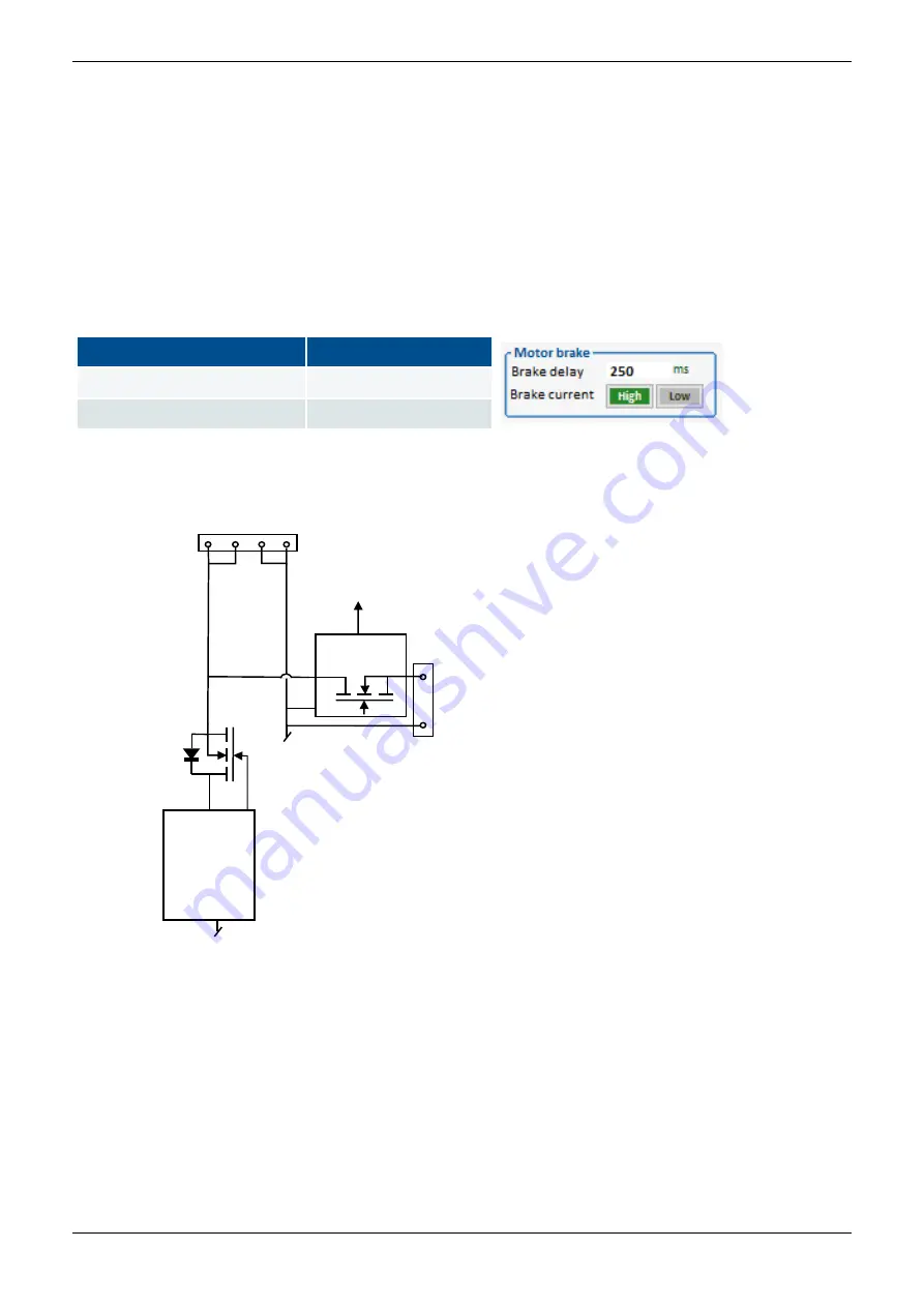
The motor brake is supplied from the internal power supply or from X7. The motor brake current
through the power switch can be configured to high or low, which optimises open circuit detection of
the used brake.
Table 8
Brake current settings
Brake current
Setting
Less than 2 A
Low
More than 2 A
High
The following figure shows a simplified circuit diagram (IMD with internal power supply) of the relevant
internal connections to X2:
X2: Motor
brake
X7: 24 V DC
+
-
Over-current
protection
Internal
power
supply
Brake OK
Power
switch
The power switch has overcurrent, short-circuit protection, as well as open circuit detection.
The over-current and short-circuit protection are based on the switch temperature, approximately 8 A.
The short-circuit initial current is higher.
NOTE
The current limit
from the internal power supply is approximately 6 A. If there is a 24 V backup
connected to X7, a short-circuit (initial) or excessive current will be drawn from the external power
supply.
The brake OK signal indicates No open circuit and temperature not too high. It is shown in the IMD
Manager and available in CAN.


