9
3. Air-termination rods for metal roof
3.1 Installation
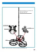
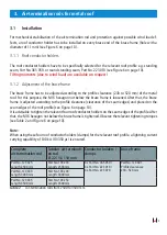
For mechanical stabilisation of the air-termination rod and protection against possible wind load ef-
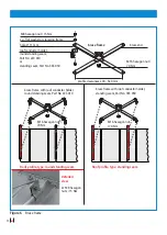
fects, a roof conductor holder has to be installed on every brace end of the brace frame (hole with a
diameter of 11 mm) (see Figure 6 on page 10).
3.1.1 Roof conductor holders
The roof conductor holders have to be specifically selected for the relevant roof profile e.g. standing
seam, Part No. 365 059, or round standing seam, Part No. 223 010 (see Figure 6 on page 10).
Tilting moments (due to wind load) are available on request!
3.1.2 Adjustment of the brace frame
The brace frame has to be adjusted according to the profile clearance (230 to 520 mm) of the metal
roof. For this purpose, the M16 hexagon nut below the brace frame is loosened. After that, the brace
frame is adjusted according to the profile clearance (clearance of the seam edges) and placed on the
seam edges of the roof profile (see Figure 6 on page 10).
It is advisable to tighten the relevant four roof conductor holders on the seam edges of the profile. After
that, the M16 hexagon nut below the brace frame is tightened. Observe the relevant tightening torques
(see Table 2 and Figure 6 on page 10).
Note:
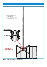
When using these four roof conductor holders (clamps) for the relevant roof profile, a lightning current
carrying capability of 100 kA (10/350 µs) is ensured.
Complete
air-termination rod
Tubular air-terminati-
on rod
Ø 22 / 16 / 10 mm
Conductor holders /
clamps
Brace frame
Part No. 123 425
Length: 2500 mm
Part No. 103 233
Length: 2500 mm
4 x Part No. 365 059 /
4 x Part No. 223 010 /
4 x Part No. 223 070
Part No. 123 401
Profile clearances:
230 - 520 mm
Part No. 123 430
Length: 3000 mm
Part No. 103 243
Length: 3000 mm
Part No. 123 435
Length: 3500 mm
Part No. 103 253
Length: 3500 mm
Table 2
Air-termination rods from 2500 to 3500 mm
Содержание 102 010
Страница 15: ...15 Notizen ...
Страница 31: ...15 Notes ...


