


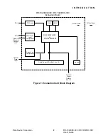


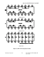


QUICK START GUIDE
The Evaluation Board comes configured as specified in Table 1. The initial
set-up requires a DC power supply, A.C. source and an 11.8 Vrms Line to
Line Resolver (or equivalent). See Figure 3 for typical test set-up diagram.
+5 VDC
150 mA
GND
+5V
Power Supply
RD-19230EX
or
RD-19240EX
GND
+5V
2-26 Vrms
1-5 Khz
RH
RL
Reference
S4
S2
S1
S3
RH
RL
Resolver (or Equivalent)
11.8 Vrms Line to Line Signal
Input Signal
Figure 3. Resolver (or Equivalent) 11.8 Vrms Line to Line Signal
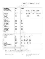
Table 1. Factory Pre-Configuration
RD-19230EX-300
RD-19240EX-300
D.C. Power Supply
+5V (150ma min.)
+5V (150ma min.)
Signal Input
11.8 Vrms Resolver
11.8 Vrms Resolver
Reference Input
2-26 Vrms
2-26 Vrms
Reference Frequency
1-5 kHZ
1-5 kHZ
Resolution
16 Bit
14 Bit
Bandwidth 130HZ
130HZ
Tracking Rate
2.5 RPS
2.5 RPS
R-S to D Converter
RD-19230FX-303
RD-19240LS-300
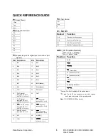
Table 2. LED Indicators
LED’s Description
Location
L1 thru L16
Digital Output Word
L1 = MSB (Most Significant Bit)
L16 = LSB (Least Significant Bit) RD-19230EX-300
L14 = LSB (Least Significant Bit) RD-19240EX-300
Example:
236.25 degree’s =LED’s L1, L3, L5 on, all others off.
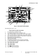
See Figure 2,
Location 7
L17
Bit Indicator(Built In Test) The BIT LED will illuminate if a
fault condition exists. (See Converter Data Sheet)
See Figure 2,
Location 8
Data Device Corporation
4
RD-19230EX-300 / RD-19240EX-300
User’s
Guide
Содержание RD-19230EX-300
Страница 8: ......


