background image

dCS Vivaldi Transport

 User Manual 

Software Issue 1.2x 


April 2015 


Vivaldi Transport Manual v1_2x 

Page 8

 English 

version


1B

S

TEP

-

BY

-S

TEP 

G

UIDE


This section guides you through setting up the unit for basic operation.  

14B

Preliminaries                

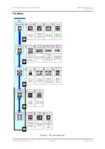
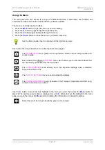
The Menu Guide sheet details the menu structure.  

For digital interfaces, use with cables designed for digital audio: 

  for AES/EBU interfaces use 110

Ω

 screened, twisted pair cables fitted with one male XLR 

connector and one female XLR connector. 

  for SDIF, Word Clock or SPDIF BNC interfaces, use 75

Ω

 coax cables fitted with BNC plugs. 

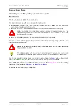
!


SDIF-2 and Word Clock interfaces require a simple DC-coupled connection. The 
interfaces may malfunction or not work at all if capacitor coupled cables or cables with 
built-in networks are used. 

  for SPDIF RCA interfaces, use 75

Ω

 coax cables fitted with RCA Phono plugs. 


Connect the power cable supplied to the power inlet on the Transport rear panel, plug the other end 
into a convenient power outlet.  

!


Please do not use an excessively heavy or inflexible power cable as this may damage 
the power inlet connector. 


The cables supplied with the unit are “commercial grade”, because most owners will 
have their own “audiophile grade” cables or will prefer to make their own cable choices. 

Set the rocker switch near the mains inlet to the 

I

 position. Press the 

Power

 button – the unit will 

display 

Vivaldi Transport

. Wait about 30 seconds while the Transport configures itself.  

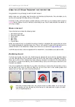
If the unit is likely to be set in an unfamiliar state, you can run the 

Factory Reset

 routine by pressing 

the buttons in this sequence:  

Menu, 

,  

, Menu, 

, Menu.


Wait a few seconds while the unit resets itself. 

Содержание Vivaldi Transport

Страница 1: ...ten permission of dCSF 1 F Any person who does any unauthorised act in relation to this publication may be liable to criminal prosecution and civil claims for damages Information contained in this manual is subject to change without notice and whilst it is checked for accuracy no liabilities can be accepted for errors 1 dCS is Data Conversion Systems Ltd Company registered in England No 2072115 dC...

Страница 2: ...dCS Vivaldi Transport User Manual Software Issue 1 2x April 2015 Vivaldi Transport Manual v1_2x Page 2 English version ...

Страница 3: ...er Clock 12 17BSTEP 3 Playing a Disc 13 18BFurther suggestions 13 Front Panel 14 19BRemote Control Receiver 14 20BDisplay 14 21BPower Button 15 22BMenu Button 15 Layer Button 16 24BPlay Pause Button 16 25BRwd Button 16 26BFwd Button 16 27BStop Eject Button 16 28BCD Tray 16 Rear Panel 17 29BAES Digital Outputs 17 30BSPDIF Digital Outputs 17 31BSDIF 2 Digital Interface 17 32BWord Clock Input Output ...

Страница 4: ... Vivaldi Transport Manual v1_2x Page 4 English version 5BSpecification 25 6BMaintenance and Support 26 Service and Maintenance 26 Replacing a Blown Mains Fuse 26 Cleaning the case 26 43BLimited Warranty 27 44BIf you need more help 28 45BSoftware History 28 Index 29 ...

Страница 5: ...ible replacement packaging can be ordered from dCS or our distributors Details can be found on our web site at www dcsltd co ukH A dCS Premium remote control is supplied with the Vivaldi DAC it is available as an optional extra 8BPositioning the unit For best sound quality the units in the Vivaldi range are designed to be mounted on separate shelves of a rack although they may be stacked directly ...

Страница 6: ...check that it has been set to the correct operating voltage for your mains supply The unit s voltage setting is shown on the serial number label If this does not match your local supply voltage DO NOT attempt to use the unit Contact your dealer to have the unit reset Using the unit with the wrong mains setting for your local supply may result in serious damage to the unit and will invalidate the w...

Страница 7: ...mpting to play such discs 13BWhich types of disc can NOT be played dCS cannot accept responsibility for any difficulty encountered while attempting to play the following types of disc Scratched damaged or dirty discs Non circular discs such as square or heart shaped Printed or labelled CD Rs or discs contaminated with glue or other sticky substances Contaminated discs may get stuck to the turntabl...

Страница 8: ...s or cables with built in networks are used for SPDIF RCA interfaces use 75Ω coax cables fitted with RCA Phono plugs Connect the power cable supplied to the power inlet on the Transport rear panel plug the other end into a convenient power outlet Please do not use an excessively heavy or inflexible power cable as this may damage the power inlet connector The cables supplied with the unit are comme...

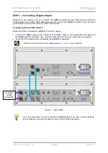
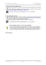
Страница 9: ...cting the Dual AES interface When used with a Vivaldi DAC AES1 2 is the main output Connect the AES1 output on the Transport to the AES1 input on the Vivaldi DAC rear panel and the AES2 output to the AES2 input using two XLR cables Ensure the cables are not swapped Press the DAC s Input button repeatedly until AES1 2 is displayed The DAC will lock to the source displaying the Audio Sync icon and D...

Страница 10: ...CH1 input on the DAC and the CH2 output to the CH2 input using two BNC cables Connect the Transport s Word Clock Out to the Word Clock In1 connector on the DAC Ensure the cables are not swapped Press the DAC Input button repeatedly until SDIF 2 appears on the display The DAC will lock to the source displaying the W1 Sync icon and 0 44 1 Why does the DAC display 0 44 1 Is the Transport faulty No th...

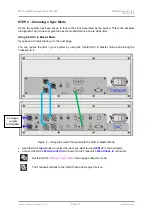
Страница 11: ...er Mode If you have a Vivaldi Clock go to the next page You can reduce the jitter in your system by using the Vivaldi DAC in Master mode and slaving the Transport to it Figure 2 Using the Vivaldi Transport with the DAC in Master Mode Use the DAC s Input button to select the input you want to use AES1 2 in the example Connect the DAC s Word Clock Out connector to the Transport s Word Clock In conne...

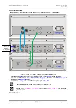
Страница 12: ...ther Use the DAC s Input button to select the input you want to use AES1 2 in the example Connect one of the Clock s Group 1 Word Clock Outputs to the Transport s Word Clock Input and the DAC s Word Clock Input 1 Use the Clock s Freq1 button to set the Group 1 outputs to 44 1kHz The Transport will lock to the Word Clock and display this icon Set the DAC s Settings Sync Mode menu page to Word Clock...

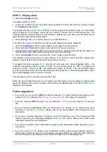
Страница 13: ...isplay PGM Mode then 0PGM0 As an example press 6 or 06 the display will change to 6PGM1 Press 8 or 08 the display will change to 8PGM2 The remote Clear button cancels the last track entry Start the disc to play the track sequence To cancel Program Mode press the remote Program button or open the CD tray The next step is crucial sit back and enjoy the music When you have finished listening you can ...

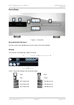
Страница 14: ...9BRemote Control Receiver Aim the remote control handset towards the receiver A for best sensitivity 20BDisplay In normal use the display B is split into 4 areas 1 2 3 4 Area 1 The symbol indicates the mechanism status Stop Eject Play Pause Fast Forward x2 Fast Reverse x2 Fast Forward x4 Fast Reverse x4 Fast Forward x8 Fast Reverse x8 A B C D E F G H I J ...

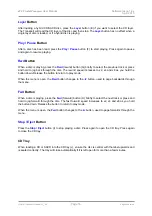
Страница 15: ... in the Menu section on page X19X To avoid unnecessary display wear we recommend switching off or setting the unit to Sleep mode at the end of the listening session 21BPower Button To switch on ensure the rear panel switch is set to I and press the Power button C on the front panel once Note that the unit cannot be turned on from the remote control To set the unit to sleep mode press the Power but...

Страница 16: ...ases to x2 x4 and x8 as you hold the button down Release the button to return to play mode When the menu is open the Rwd button changes to the button used to page backwards through the menu 26BFwd Button When a disc is playing press the Fwd forward button H briefly to select the next track or press and hold to jog forward through the disc The fast forward speed increases to x2 x4 and x8 as you hol...

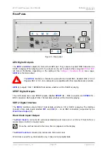
Страница 17: ...1 AES EBU format data whether a CD or SACD is playing 30BSPDIF Digital Outputs The unit features two co ax SPDIF outputs labelled SPDIF1 M RCA connector and SPDIF2 N BNC connector Both output 16 44 1 format data whether a CD or SACD is playing 31BSDIF 2 Digital Interface The SDIF 2 interface outputs 16 44 1 format data whether a CD or SACD is playing The interface consists of two data inputs label...

Страница 18: ...d the list of remote control commands from www dcsltd co ukH The interface is designed to be used with a straight through cable wired pin 1 to pin 1 etc The pin connections are Pin 2 dCS unit transmit Pin 3 dCS unit receive Pin 5 ground Shell cable screen drain wire We recommend using infra red remote control instead Mains inlet Power is connected via a standard IEC320 connector S protected by a f...

Страница 19: ...ve Restore Factory Reset Locks some important settings Saves the current config to memory Loads the previously saved config from memory Restores standard factory settings Displays the unit status Displays the software issues serial number Displays dCS contact details Loads new software from a dCS CD Display Settings Brightness Display On Off Sets the display brightness Turns the main display on of...

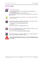
Страница 20: ...five top level menu pages The INFORMATION menu gives unit set up details software issues serial number and contact details Each model has a different SETTINGS menu which allows you to set some features that are not directly accessible from the front panel The CONFIGURATION menu allows you to lock important settings save a standard setup and reset the unit The DISPLAY SETTINGS menu is used to adjus...

Страница 21: ...the software versions loaded in the unit Please have this information ready if you contact your dealer for any reason Control Board 1 xx this is the main software version Front panel 1 xx This page does not time out press the Menu button to exit Contact The Contact page displays the dCS web site URL and support email address This page does not time out press the Menu button to exit If you have any...

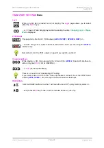
Страница 22: ...r electrical environment when you are using the AES1 2 interface only Remember to turn the PCM outputs on again if you want to use them Upsampling Mode While playing a CD this page sets the format of the AES1 2 Dual AES interface to either encrypted DSD 1 bit at 2 822MS s or DXD 24 bits at 352 8kS s There is no need for an Upsampling Off setting If you want to listen to the 16 44 1 data unprocesse...

Страница 23: ... setup later and want to keep it select Save again to store the changes Restore Configuration If the unit settings are accidentally changed select Restore to reload the settings you saved earlier Factory Reset Resets the unit to standard settings These are PCM Enable to On Upsample Mode to DSD Brightness to maximum Display to On RS232 Mode to Binary DISPLAY SETTINGS Menu Brightness Set the display...

Страница 24: ...ls while the display shows In Phase Press the Menu button the noise on the right channel is inverted while the display shows Out of Phase The first burst should produce a central image the second burst should not If these are the wrong way around one channel in your system is phase inverted Press the or button to stop the test and return to the menu Burn In A procedure to condition your system The...

Страница 25: ...on 2x BNC connectors outputs 16 44 1 data whether a CD or SACD is playing Clocking Word Clock Output on 1x BNC connector With the transport in Master mode a TTL compatible 44 1kHz word clock derived from the internal crystal oscillator is available on this output The calibration accuracy when shipped is 10ppm not temperature compensated Calibration usually remains stable for several years Word Clo...

Страница 26: ...ic shock and will invalidate the warranty Fuse failure is rare Referring to the diagram below remove the power cable use your fingernails to catch the two tabs of the fuse holder A push them together to release the clips and pull the fuse holder out Pull out the blown fuse from the lower position B and discard it Either move the Spare Fuse C to the lower position or fit one of the fuses from the m...

Страница 27: ...are carried out the product is not used in accordance with the Operating Conditions stated in this manual the product is serviced or repaired other than by dCS or our authorised service agents the product is operated without a mains earth or ground connection the unit is returned inadequately packed dCS reserve the right to apply a service charge if a product returned for warranty repair is found ...

Страница 28: ...ing new software Occasionally a hardware upgrade may be necessary also to increase the capacity of the electronics add extra connectors or extra front panel controls Please note that not all software updates produce an audible improvement We recommend that you keep your software up to date Check the dCS web site occasionally for news of the latest software updates Update discs are available from o...

Страница 29: ...ion 23 display 23 generator 24 information 21 PCM enable 13 settings 22 upsampling mode 13 using 20 menu back button 16 menu button 15 menu forward button 16 O operating conditions 27 output AES3 10 17 connecting 9 Dual AES 9 17 SDIF 2 10 17 SPDIF 10 17 word clock 17 P PCM enable 22 phase check 24 play pause button 16 playing a disc 13 positioning 5 power button 15 power off 15 power up 8 R rear p...

Отзывы: