background image


INTRODUCTION 

UNIT OVERVIEW 


  The DC SOLUTIONS model MEGA-ARM barrier style parking gate operator is unique in the 
industry. Setting the MEGA-ARM apart are many features that make it the front runner in its class.  
With standard features like: 


• 

Built in battery backup - inherent  24 VDC backup power with regulated 24VDC for accessories. 

• 

High torque 24 volt Permanent Magnet DC motor . 

• 

Full service controller with eight inputs and LED indicators for loops, card reader, radio, etc... 

• 

Continuous duty operation for all applications (6k per day, SPRINT version 10k per day). 

• 

Reversible arm direction for right or left handed operation. 

• 

Instant Reverse Device 

(IRD)

 monitor senses obstructions going open and close. 

• 

Automatic open of gate arm when power is lost if desired (With 15 sec. delay selection). 

• 

Raise gate input memory will memorize multiple vehicles-ideal for barcode scanners & AVI. 

• 

Ability to have arm STOP in close travel if  tail-gating is sensed at close loop. 

• 

Anti-tail gate alarm - fires K1 relay to trigger a warning device when tail-gating is sensed. 

• 

Interlock with memory- allows Mega Arm to open a slide/swing gate first then raises arm. 

• 

Break away mounting design for the 12 -15 foot by 3 "tubular aluminum boom arm. 

• 

All rust proof aluminum construction with white powder coat baked on enamel. 

• 

Molded Polyethylene UV stabilized cover never needs wax or paint  

• 

Direct drive gear reducer eliminates many parts that might otherwise fail. 

• 

Microprocessor (RISC) based electronics with watch dog reset timer. 

• 

State of the art MOSFET motor drive technology, NO contactors or relays.   

• 

Dynamic motor braking to preserve arm positioning. 

• 

Soft start and stop in open and close travel motions. 

• 

No limit switches to fail-uses magnetic (Hall Effect) sensors to monitor arm position. 

• 

Maximum Run Timer for motor (MRT) with anti-tamper protection in closing direction. 

• 

Each unit configurable as master or slave operator. 

• 

Safe 24 VDC low voltage motor and control wiring. 

• 

Open architecture PCB with space for OVERDRIVE CPU for future expanded options. 

• 

LED diagnostic center for easy on-site trouble shooting. 

• 

Closing timer adjustable from 1-33 seconds with on / off selection. 

• 

Tranzorb diodes on all inputs for protection against transient voltage spikes. 

• 

Capable of being powered by 120 VAC, 220 VAC or Solar power, standard. 

• 

Duplex outlet gives convenient supply of 120 VAC for transformers and 120 VAC accessories. 

• 

10

 year perforation warranty on cover and chassis with 

2

 years on electronics and mechanism. 


INSTALLATION PROCEDURE 


CONCRETE PAD   


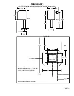
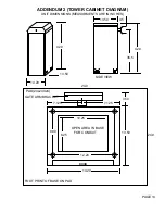
  The concrete pad for operator mounting should be approximately 24"x24"x24"  in order to provide adequate 
weight and structure to insure proper and stable operation. Pad should be 6" above finished grade or even with 
top of curb if one is present.

 (NOTE: PAD SHOULD ALWAYS GO BELOW FROST LINE IN REGIONS 

WHERE GROUND WILL FREEZE!!)  


ANCHORS (MOUNTING UNIT)


Proper anchors for fastening operator to pad will be a 1/2"x6" wedge anchor patterned to match the mounting 

base of  the unit. They should be installed with approximately 1.25" showing above concrete surface in order to 
allow for the 1/2” thick base plate as well as washers for leveling.                                                                                     


PAGE 1


Содержание MEGA ARM

Страница 1: ... COVERS THE NEW INTER LOCK MEMORY FEATURES WARNING CHILDREN SHOULD NEVER BE ALLOWED TO PLAY NEAR OR OPERATE AUTOMATIC GATES FAILURE TO OBSERVE SAFE OPERATING PROCEDURE TRAIN YOUR CUSTOMER PROPERLY OR INSTALL PROPER WARNING SIGNAGE MAY RESULT IN SERIOUS INJURY DC SOLUTIONS INC 590 SAWGRASS CORPORATE PARKWAY SUNRISE FLORIDA 33325 PHONE 954 846 9488 FAX 954 846 9464 MEGA ARM MEGA PULSE MEGA SENSE MEG...

Страница 2: ...1 S2 MODE SELECTIONS S1 5 MODE SELECTIONS S2 5 CLOSE TIMER SELECTION S2 5 ADJUSTMENTS INSTANT REVERSE DEVICE IRD 6 GATE ARM LEVELING 6 TROUBLE SHOOTING AND MAINTENANCE PROCEDURES BATTERY CHECK OUT 7 GATE NOT OPERATING 7 GENERAL SERVICE 7 SHEAR PIN REPLACEMENT 6 SAMPLE CONFIGURATIONS FREE EXIT OPERATION 8 ENTRY WITH ACCESS CONTROL DEVICE 8 DUAL DIRECTION 8 INTERLOCK MEGA ARMS OR WITH OTHER OPERATOR...

Страница 3: ...tch dog reset timer State of the art MOSFET motor drive technology NO contactors or relays Dynamic motor braking to preserve arm positioning Soft start and stop in open and close travel motions No limit switches to fail uses magnetic Hall Effect sensors to monitor arm position Maximum Run Timer for motor MRT with anti tamper protection in closing direction Each unit configurable as master or slave...

Страница 4: ... external control devices must have normally open dry contacts DO NOT CONNECT ANY DEVICE WHICH WOULD DELIVER ANY VOLTAGE OF ANY KIND TO THESE TERMINALS Terminals 9 10 11 12 are the commons 0 VDC used to activate the following inputs 1 2 3 OPEN These inputs will trigger gate open when pulsed or hold gate open with maintained contact When released gate will close if closing timer is on or if close i...

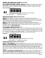
Страница 5: ...iver RELAY OUTPUT K1 OPTION S1 6 off S1 8 off relay will fire latch when gate is not closed S1 6 on S1 8 off relay will fire when arm is pushed up off of limit switch use with slip clutch option and fires relay when a tail gate is detected by the close loop ANTI TAIL GATE ALARM S1 6 off S1 8 on relay will pulse relay when arm reaches full open position S1 6 on S1 8 on relay will only pulse when in...

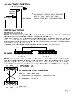
Страница 6: ...ster gate J5 terminal 12 to slave gate J5 terminal 12 EXAMPLE If only open and close are used at master then three wires will run between gates 1 2 3 4 5 6 7 8 9 10 11 12 1 2 3 4 5 6 7 8 9 10 11 12 MASTER J5 SLAVE J5 OPEN CLOSE COMMON EXAMPLE STEP 3 If it is required that if one gate senses an obstruction the other reverses also then 3 additional wires must be run between the master J3 and slave J...

Страница 7: ... the obstruction sensor has reversed and re opened the arm or if the S2 7 timer to close is turned on The default will keep the gate up for 4 seconds to allow the vehicle to be moved from the gate arm path Changing settings 1 5 will increase or decrease this hold open time The default of 3 ON and 1 2 4 5 OFF will provide a 4 second close time delay SECONDS 1 2 4 8 16 S2 1 2 3 4 5 6 7 8 SHOWS DEFAU...

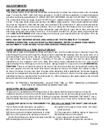
Страница 8: ...ed this can be done through adjustment to the magnetic cam arm Note that during these adjustments the arm only travels approximately 85 to 89 degrees for its full motion Always adjust for a level arm in the HORIZONTAL POSITION There is a small set screw in the side of the cam arm which can be loosened to allow the cam arm magnet to reach the close limit sensor located on back of controller H2 earl...

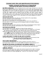
Страница 9: ...ts are wired correctly test S 3 manual open switch GATE DEAD NO OPERATION 1 Check LED D14 for AC power indication and check AC power switch is on 2 Check LED D11 for Heart Beat pulses if none and D14 AC D5 Brake are on then gate has repeatedly sensed obstructions Clear obstruction then clear with next new input 3 IRD D2 LED is flashing MRT has expired H1 H2 Hall sensors and clearance to magnet on ...

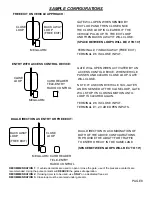
Страница 10: ...E LOOP GATE WILL STOP ITS CLOSING MOTION UNTIL LOOP IS CLEARED AGAIN DUAL DIRECTION IS A COMBONATION OF BOTH OF THE ABOVE CONFIGURATIONS TO PROVIDE THE ABILITY FOR TRAFFIC TO ENTER OR EXIT IN THE SAME LANE TERMINAL 7 IS BACKAWAY FREE EXIT TERMINAL 6 IS CLOSE INPUT TERMINAL 6 IS CLOSE INPUT TERMINAL 1 2 3 ARE OPEN INPUTS BACK AWAY LOOP FREE EXIT BACK AWAY LOOP FREE EXIT CLOSE LOOP SPACE BETWEEN LOO...

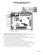
Страница 11: ...F4 F3 IRD AND MRT U3 OVER DRIVE CPU 1 C 2 NC 3 NO 4 24VDC REGULATED TX BLK RED YEL YEL BLU ORG Q3 Q4 Q5 Q6 RELAY OPTIONAL MODE 5 8 I O INTERFACE PORT 24VDC REQULATED 1 AMP DC F1 J5 ACCESSORY POWER IS 24VDC REGULATED RATED AT 500 ma 1 2 AMP POWER AT ACCESSORY AND AT RELAY PIN 4 IS FUSED AT F1 WITH A 1 AMP FAST BLO FUSE NOTE J5 8 IS NOW THE INTERLOCK WITH MEMORY INPUT SEE PAGE 13 D11 HEART BEAT SHOW...

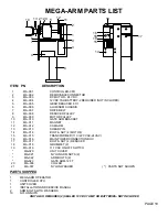
Страница 12: ...1 MAGNET 12 MA 012 CAM ARM 13 MA 013 SHEAR PIN 14 MA 014 BOLT NUT 4 MOTOR 15 MA 015 TRANSFORMER 110 220 VAC 24VAC 16 MA 016 MAIN POWER CONNECTION BOX 17 MA 017 BOLT NUT 4 REDUCER 18 MA 018 GROMMET 2 19 MA 019 117 VAC ON OFF SWITCH MA 020 UNIT COVER MA 021 NYLON ARM NUTS 2 MA 022 ARM BOLTS 2 MA 023 GATE ARM 12 FT 20 MA 036 COLLAR 21 MA 037 NYLON WASHER PARTS NOT SHOWN PARTS SHIPPED 1 MEGA ARM OPERA...

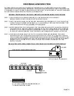
Страница 13: ...HE STEPS ABOVE THE CAM ARM WHICH ADJUSTS THE LIMITING POINTS OF THE ARMS TRAVEL MUST BE TURNED 90 DEGREES TO THE LEFT WHEN VIEWED WHILE STANDING IN FRONT OF THE CONTROL BOARD CAM ARM NOW POINTS IN THE DIRECTION OF THE ARM AND IS LEVEL WITH MOUNT BRACKET NOTE THE SMALL LIMIT SENSORS ON THE BACK OF THE PCB STEP 4 NOW CHECK TO MAKE SURE THAT S1 7 IS ON MOTOR WIRES ARE REVERSED THE CAM IS ADJUSTED AND...

Страница 14: ...INCHES 41 5 17 5 20 25 15 75 41 5 8 0 20 25 13 5 9 0 4 21 5 3 5 3 5 3 5 FOOT PRINT OF BASE ON PAD 9 0 34 75 36 5 8 0 INSIDE POST 5 5 5 5 5 PAD 24x24 6 0 3 25 12 0 12 0 THESE DIMENSIONS WILL CENTER THE OPERATOR ON THE PAD CENTER LINE 2 0 8 0 PAGE 12 ...

Страница 15: ...MENSIONS MEASURMENTS ARE IN INCHES 42 0 3 5 FOOT PRINT OF BASE ON PAD 36 5 PAD 24x24X24 SIDE VIEW 14 20 42 0 13 50 13 50 24 0 24 0 DOOR 10 25 8 25 OPEN AREA IN BASE GATE ARM BRACKET 7 125 7 125 14 20 13 50 FOR CONDUIT 12 20 9 90 3 50 PAGE 13 ...

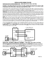
Страница 16: ...es from the MEGA ARMs K1 relay common normally open to the other operators common and open input WARNING max of 30 VOLTS 5 AMPS THROUGH RELAY J5 8 was the unused SHADOW LOOP input on the MEGA ARM Note A separate open device 24 hour timer toggle switch can be run to the other operator to control it without raising the gate arm Tampering with the other operators safety loops safety edges and reverse...

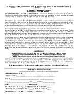
Страница 17: ... suitable for a particular purpose In no event shall DC Solutions inc be held liable for direct indirect incidental special consequential damages or loss of profits whether based on contract tort or any other legal theory during the course of the warranty or at any time there after The installer and or end user agree to assume all responsibility for all liability in use of this product releasing D...

Отзывы: