CORTO-C INSTALLATION GUIDE | PAGE
2
OF 6
CORTO-C
650, 850
INSTALLATION INSTRUCTIONS
SAFETY
This appliance is not intended for use by persons (including children) with reduced physical, sensory or mental capabilities, or lack of experience
and knowledge, unless they have been given supervision or instruction concerning use of the appliance by a person responsible for their safety.
Children should be supervised to ensure that they do not play with the appliance.
WARNING: In order to avoid a hazard for very young children, this appliance should be installed so that the lowest heated rail is at least 600mm
above the floor.
ELECTRICAL
• Must be installed by a registered electrician.
• The 12V ‘safety isolating’ transformer supplied must be located in a dry accessable location (do not cover with insulation).
• Distance from transformer to towel rail must be less than 2 metres (see FAQ’s).
• Typical transformer locations include: Ceiling cavity / Wall cavity (behind switch plate) / Cupboard.
• Means for disconnection must be incorporated in the fixed wiring in accordance with wiring guidlines AS/NZS 3000:2000.
• The waterproof wirenut connectors provide an IPX7 rating.
• The towel rail may be installed in wet area electrical zones 1, 2 & 3 as specified in AS/NZS 3000:2000.
• Manufactured and tested to AS/NZS 60335.2.43.
• Minimum 50 mm clearance to surrounding surfaces.
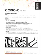
1. WALL PREPARATION
• Corto-C heated towel rails may be fixed to ANY type of wall, timber stud, steel stud or masonry (solid or cavity).
• Stud walls (timber or steel) require timber nogs at the correct position for all legs. See table 1.0 for fixing dimensions.
• If the precise position can’t be determined early in the job, consider nogging with 18mm construction ply, covering a larger area.
• Be aware that attempting to fix into plasterboard or cement sheeting alone is NOT recommended. Plasterboard (in particular) will not hold long term.
2. PRE WIRING
• First determine which side (left or right) you would like the cable to enter the heated towel rail.
•
In general, the leg that is closest to the transformer and farthest from wet areas. eg. top left leg if the transformer is in the ceiling and shower is to the right.
• For stud walls drill a 10mm hole in the noggin for the low voltage wiring supplied at the leg position chosen. Typical layout see Table 1.0 for fixing dimensions.
DCS
CORTO 350, 550, 750
Electricians, please ensure a copy of the installation
instructions is left with the end user for future reference
insTallaTiOn insTRUCTiOns
saFeTY
This appliance is not intended for use by persons (including children) with
reduced physical, sensory or mental capabilities, or lack of experience and
knowledge, unless they have been given supervision or instruction concerning
use of the appliance by a person responsible for their safety. Children should
be supervised to ensure that they do not play with the appliance.
WARNING: In order to avoid a hazard for very young children, this appliance
should be installed so that the lowest heated rail is at least 600 mm above the
floor.
eleCTRiCal
• Must be installed by a registered electrician.
• The 12V ‘safety isolating’ transformer supplied must be located in a
dry accessable location (do not cover with insulation).
• Distance from transformer to towel rail must be less than 2 metres.
see *FAQ’s
• Typical transformer locations include:
- ceiling cavity
- wall cavity (behind switch plate)
- cupboard
• Means for disconnection must be incorporated in the fixed wiring in
accordance with wiring guidlines AS/NZS 3000:2000.
• The waterproof wirenut connectors provide an IPX7 rating
• The towel rail may be installed in wet area electrical zones 1, 2 & 3 as
specified in AS/NZS 3000:2000.
• Manufactured and tested to AS/NZS 60335.2.43
• Minimum 50 mm clearance to surrounding surfaces.
1. Wall PRePaRaTiOn
• Corto heated towel rails may be fixed to ANY type of wall, timber stud, steel
stud or masonry (solid or cavity).
• Stud walls (timber or steel) require timber nogs at the correct position for all
legs. See table 1.0 for fixing dimensions.
• If the precise position can’t be determined early in the job, consider nogging
with 18mm construction ply, covering a larger area.
• Be aware that attempting to fix into plasterboard or cement sheeting alone
is NOT recommended. Plasterboard (in particular) will not hold long term.
2. PRe WiRing
• First determine which side (left or right) you would like the cable to enter the
heated towel rail.
• In general, the leg that is closest to the transformer and farthest from wet
areas. eg. top left leg if the transformer is in the ceiling and shower is to the
right.
• For stud walls drill a 10mm hole in the noggin for the low voltage wiring
supplied at the leg position chosen. Typical layout see Table 1.0 for fixing
dimensions.
Fig 1.0
Fig 3.0
Fixed wiring
Transformer
12V wiring
Studs
Nogs
4”
G
RI
ND
ER
Fig 2.0
Holes in legs
face bottom
page 2 of 5
FIGURE 1
FIGURE 2
FIGURE 3
ELECTRICIANS
please ensure a copy of the installation
instructions is left with the end user for future reference.


