dbx 786 Скачать руководство пользователя страница 10

8

controls

Operating

786

Rear Panel

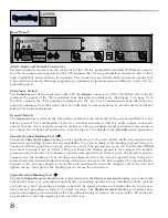
Au dio Input and Output Connectors

Each audio input connector on the rear panel of the 786 is a gold-plated Neutrik® XLR female connec-
tor. The no-compromise approach to the 786 required that we use gold-plated connectors, due to their
high conductivity and resistance to corrosion. The connectors are default wired in 

BALANCED

mode (pin

2 hot, AES convention), although supplying an unbalanced signal presents no difficulty to the 786, (by
grounding pin 3).

Un balance Switch

The 

Unbalance

switch is associated only with the 

Output

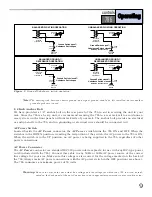
connectors of the 786. When it is in the IN

position, the output of the 786 is switched from balanced to unbalanced. (See Figure 5 on page 9.) In
the OUT position, the 786’s outputs are balanced in the “pin 2 hot” configuration. Note that when the
output is unbalanced via the switch, there is a 6dB drop in output signal level, and the meter is still cal-
ibtrated for a balanced signal. 

Ground Switch

The 

Ground

switch, when in the IN position, references the center tap of the output transformer to the

chassis ground. The combination of the two switches associated with the audio output connectors
ensures that the 786 is versatile enough to interface with any equipment and can deliver clean audio to
the output, free of hum and interference. (See the Figure 5 for details of the 

Ground

switch operation.)

Chassis Ground Binding Post

(

The green 

Chassis Ground

binding post is supplied to give the user another method to provide com-

prehensive grounding options for any installation. It is easy to think of the binding post as being syn-
onymous with the ground pin on any AC power cord. (The ground pin on an AC cord should NEVER
be removed, shorted out, or “lifted”.) The post allows the chassis ground to be connected to another
ground source if desired. (ie: a chassis ground system provided by another piece of gear) Wire may be
connected to the binding post by securing the stripped end of the wire through the hole in the post,
located under the hardened plastic nut-top of the post. Access to the hole is gained by unscrewing the
top part of the post far enough to reveal the hole underneath. Insert the stripped end of the wire and
tighten the top (nut) part of the binding post to secure the connection.

Signal Ground Binding Post

( ) 

The black 

Signal Ground

binding post is located next to the 

Chassis Ground

binding post, and works

in much the same way, providing comprehensive grounding options for any installation. Some systems
are built on a “star” grounding principle, where all the signal grounds are brought directly to one cen-
tral point and grounded to earth at the same location. The 

Signal Ground

binding post allows easy

access to the signal ground system of the 786 without having to remove the cover of the 786 and locate
a good place to take the signal ground out of the box.

MANUFACTURED UNDER THE FOLLOWING U.S. PATENTS:
4,368,425  5,282,252.  OTHER PATENTS PENDING.

Содержание 786

Страница 1: ...Precision Mic Preamp 786 Owner s Manual...

Страница 2: ...t or in the system to which it is connected can result in full line voltage between chassis and earth ground Severe injury or death can then result if the chassis and earth ground are touched simultan...

Страница 3: ...nsole Signal Path 3 Connection To Your System 4 Operating Controls 6 Front Panel Description 6 Rear Panel Description 8 Technical Support Factory Service 10 Warranty 11 Specifications 11 Block Diagram...

Страница 4: ...in mind We wanted to create a pristine mic pre that would carefully reveal the very subtle nuances of any source device To that end the 786 uses premium parts and as short a signal path as possible t...

Страница 5: ...t upon the signal EQ dynamics panning etc Unfortunately console preamp circuits are often not given enough room on the circuit board or high quality parts It is for this reason that outboard pre amps...

Страница 6: ...red settings including phantom power and Low Z Connect the audio output of the 786 to the console s LINE INPUT and ensure that the con sole s input selection switch is set to LINE and the console s ga...

Страница 7: ...a compressor limiter in the path before the recorder The perfect com panion product to the 786 is the dbx 160SL Stereo Compressor Also when recording with this method remember that desired gain change...

Страница 8: ...rated to the frequency at which 3dB of boost or cut occurs when the Detail con trol is set at 16dB or 16dB respectively Detail Control This control adjusts the amount of boost or cut of the high frequ...

Страница 9: ...or consistent performance 20dB Pad Switch and LED This switch inserts a 20dB attenuator circuit into the signal path from the microphone input The pad is inserted before the signal is routed through t...

Страница 10: ...ssis Ground Binding Post The green Chassis Ground binding post is supplied to give the user another method to provide com prehensive grounding options for any installation It is easy to think of the b...

Страница 11: ...e to any 50Hz or 60Hz AC power source of the correct line voltage for your area Make sure this voltage is also correct for the voltage marked on the back of the 786 Always make AC power connections wi...

Страница 12: ...registration card and send it in please do so now Before you return a product to the factory for service we recommend you refer to the manual Make sure you have correctly followed installation steps...

Страница 13: ...y obligation or liability in connection with the sale of this product In no event shall dbx or its dealers be liable for special or consequential damages or from any delay in the perfor mance of this...

Страница 14: ...low LED to indicated when 12 dB octave mode is selected Peak Red LED to indicated when signal is within 3 dB of clipping Sense points are out put of M8 gain module Course Gain output of Fine Control a...

Страница 15: ...in Switching Relay Bank Coarse Gain Rotary Switch 15dB 20dB 65dB M8 Mic Pre Module 48V Relay Relay Super Low Z 20dB Pad Phase Invert Relay Relay Relay Relay Rectifier Unbalance Ground Spectrum Detail...

Страница 16: ...Utah 84070 Phone 801 568 7660 Fax 801 568 7662 Int l Fax 603 672 4246 Questions or comments E mail us at customer dbxpro com or visit our World Wide Web home page at www dbxpro com A Harman Internatio...

Отзывы: