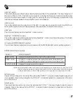
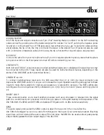
dbx 586 Скачать руководство пользователя страница 12

586

¨

Rear Panel

WIRING SCHEME
All of the input and output connectors are “pin 2 hot” meaning that pin number 2 on the XLR connecting
cables carries the positive side of the balanced signal. Pin number 3 is “cold”, carrying the negative polar-
ity and pin 1 is the shield.The 1/4”TRS jacks are wired so that when you use 3 conductor cables and bal-
anced signals, the tip is hot, the ring is cold and the sleeve is the shield. The 1/4” jacks can also be used
with 2 conductor unbalanced cables. In this case, the tip is hot and the ring and sleeve are grounded.

MIC INPUT
Connect the cable from your microphone here. If your mic requires phantom power, ensure that the phan-
tom power switch on the front panel is turned off before connecting your mic.

LINE INPUTS
Both XLR and TRS 1/4” connectors are provided and either balanced or unbalanced line-level devices may
be connected to the 586. These inputs can also be used for instrument-level devices, depending on the
status of the LINE/INST. switch (described below).

LINE/INST. switch
To connect instrument-level devices to the 586, use either the 1/4” or XLR Line Input connector and
depress the LINE/INST. switch. Doing so will increase the input impedance and the gain applied to these
inputs to make them suitable for devices using passive or piezoelectric pickups. The INST. setting also
reconfigures the Line Inputs as strictly unbalanced, pin 2 (tip) hot, pins 1 and 3 (sleeve and ring) ground-
ed.

INSERT LOOP
These connectors allow you to insert another processor such as a compressor or de-esser into the signal
path.You would insert your processor into this loop to place it in the path leading to the equalizer of the
dbx 586. Both the SEND and RETURN are balanced TRS jacks with +4 dBu nominal sensitivity.

SEND
The audio signal produced at the SEND output is taken from a point in the circuit after the 
dbx 586’s tube stages.You can run a cable from this jack to the input of your external processor. Inserting
a jack here will not interrupt the audio output.This is to allow the SEND to be used as direct post-preamp
output that bypasses the main output stage of the dbx 586.

10

¨

Содержание 586

Страница 1: ...Vacuum Tube Preamplifier 586 Owner s Manual...

Страница 2: ...he system to which it is connected can result in full line voltage between chassis and earth ground Severe injury or death can then result if the chas sis and earth ground are touched simultaneously L...

Страница 3: ...6 Introduction 2 Features 2 Inspection 3 Warranty 3 Background 4 Connecting the dbx 586 to Your System 5 Operating Controls 7 Front Panel 7 Rear Panel 10 Specifications 12 Ma anua al Co ont tent ts s...

Страница 4: ...nce and transient response The premium grade 12AU7 vacuum tubes used in the dbx 586 are hand tested and graded specifically for gain noise and microphonics Precision 1 resistors are used throughout th...

Страница 5: ...ing the product to any but the specified receptacles This warranty is void unless service or repairs are performed by an authorized service center No responsibility is assumed for any special incident...

Страница 6: ...te larger circuit boards dedicated to the mic pre resulting in better frequency and dynamic range as well as better noise specs The 586 is the perfect partner for your microphone providing you with tw...

Страница 7: ...ches the type and rating corresponding to the voltage in use as indicated on the rear panel of the 586 Apply power to the 586 Connect the AC power cord to the AC power receptacle on the back of the un...

Страница 8: ...e 586 s Line Outputs directly to the audio inputs of your recorder This will require the disconnection of the console s audio output to the specific track of the recorder 3 Enable the record function...

Страница 9: ...ing Co ont tro ols s 7 IN OUT Channel 1 MANUFACTURED UNDER THE FOLLOWING U S PATENTS 4 368 425 5 282 252 OTHER PATENTS PENDING Power Supply if required Figure 2 Connecting the 586 to a recorder SHAPE...

Страница 10: ...gnal For minimal tube saturation cleanest possible sound use relatively low settings of the DRIVE control and higher settings of the LEVEL control Moderate amounts of tube character can be achieved wi...

Страница 11: ...e METER SOURCE switch settings as shown METER SOURCE switch setting Selection What is displayed NOTE When the OUTPUT LEVEL meter source switch is selected 0 VU corresponds to an output level of 4 dBu...

Страница 12: ...us of the LINE INST switch described below LINE INST switch To connect instrument level devices to the 586 use either the 1 4 or XLR Line Input connector and depress the LINE INST switch Doing so will...

Страница 13: ...s use of the equalizer limiter and digital output option This input source would be select ed by enabling the insert switch on the front panel LINE OUTPUTS Both XLR and TRS 1 4 connectors are provided...

Страница 14: ...cally balanced unbalanced RETURN Impedance SEND 100 balanced 50 unbalanced RETURN 40k balanced 20k unbalanced Nominal Send Level 4 dBu Nominal Return Level 4 dBu SYSTEM PERFORMANCE DRIVE Control Range...

Страница 15: ...ly when the optional dbx TYPE IV module is installed in the unit DITHER See manual for dbx Type IV option SHAPE See manual for dbx Type IV option REAR PANEL SWITCHES INST Switches the gain and impedan...

Страница 16: ...Utah 84070 Phone 801 568 7660 Fax 801 568 7662 Int l Fax 603 672 4246 Questions or comments E mail us at customer dbxpro com or visit our World Wide Web home page at www dbxpro com A Harman Internati...

Отзывы: