8
ENGLISH
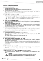
DVA M2M – Functions and controls
"Balanced Audio" section
2)
" INPUT” INPUT CONNECTOR
Audio balanced input at line level. It is able to accept “XLR” sockets.
3)
"LINK” OUTPUT CONNECTOR
The “XLR” connector connected in parallel with input (1) can be used to send the input audio
signal to another amplified speaker.
"Status" section
4)
“LIMITER” INDICATOR LIGHT
This indicator comes on red to indicate that the internal limiter circuit has tripped.
This prevents amplifier distortion and protects the speakers against overloads.
Always avoid operating conditions where the system works for long periods of time
with LED flashes or it is always ON
5)
“SIGNAL” INDICATOR LIGHT
This indicator comes on green to indicate the presence of an input signal to a level higher
than -20dBu.
6)
“MUTE/PROT” INDICATOR LIGHT
This yellow indicator indicates amplifier status. In normal operating conditions, the LED is off;
if it flashes or is always on, refer to the diagnostics table to check amplifier status.
7)
“READY” INDICATOR LIGHT
This indicator comes on green to indicate that the main power voltage is correct. In normal
operating conditions, the LED is on; if it flashes or is off, refer to the diagnostics table.
"Audio Input control " section
8)
“INPUT SENS” INPUT SENSITIVITY CONTROL
This control regulates the sensitivity of the signal amplifier input and of the connected
DVA M2S passive speaker.
This control does not affect the “LINK” (2) output level
"DSP configuration" section
9)
“DSP Preset” 10-position ROTARY SWITCH
This 10-position rotary switch makes it possible to select the nine preset equalization curves
(selector 0-8)
Position 9 ("user") is reserved for advanced operations such as firmware update. Therefore in
this position, the speaker is not operating and the amplifier is set to mute.
"Service" section
10) “Service Data USB” Connector
Via this USB connector, it is possible to update the firmware of the DVA M2M amplifier
module using the computer and a dedicated program.
"Slave Audio Output" section
11) Amplified output for the speaker DVA M2S (4-pole connector)
The connection between the speakers DVA M2M and DVA M2S is realized by means of the
supplied cable.
Attention
Connect the connector only and exclusively the speaker DVA M2S
Turn off the speaker DVA M2M before connecting the speaker DVA M2S.
Содержание DVA M2M
Страница 28: ...DVA MINI Digital Array System 27 DIMENSIONI DIMENSIONS ABMESSUNGEN DIMENSIONS DVA M2S DVA M2M...
Страница 29: ...28 SCHEMA A BLOCCHI BLOCK DIAGRAM BLOCKSCHALTBILD SCHEMAS FONCTIONNELS...
Страница 30: ...DVA MINI Digital Array System 29 DVA MINI Quick configuration...
Страница 33: ...32...
Страница 35: ...34...
Страница 41: ...40...
Страница 42: ...DVA MINI Digital Array System 41...
Страница 43: ...42...


