background image


7   

  M4.2Si TimeLock User Manual 

Unpacking and Installing the M4.2 TimeLock™


Immediately upon receiving your M4.2 TimeLock™, please make a careful inspection for any shipping 
damage.  If  damage  is  found  or  suspected,  please  notify  the  carrier  at  once  and  then  contact  your 
dealer

.       

The  DaySequerra  M4.2  TIMELOCK™  is  shipped  in  one  carton,  which  contains:  the  M4.2 

TimeLock™ unit, an AC power cable, a Torx

TM

 T-8 L-key and this User Manual. 


We  strongly  encourage  you  to  save  the  shipping  carton  and  shipping  materials  supplied  with 
your M4.2 TimeLock™.

 They are specially designed to properly protect your M4.2 TimeLock™, and in 

the event that you need to return it for service, only these OEM shipping materials can ensure its safe 
return to our factory. 
 
We provide a limited 3-year warranty on all of our products, but if you don’t register your unit, it’s hard 
for  us  to  contact  you  when  software  updates  become  available. 

So  please  take  a  few  minutes  to 

complete the warranty registration form on our web site, www.daysequerra.com.

 Thank you! 


Rack Mount Installation.  

The M4.2 TimeLock™ chassis has four rack mounting holes in its chassis 

and  has  been  designed  to  fit  in  a  19”  standard  1RU  space.    Plastic  ‘finishing’  washers  are 
recommended to protect the painted finish around the mounting holes. 
 

Power Connection.  

The AC power cable supplied with the M4.2 TimeLock™ must be connected from 

the  M4.2  TimeLock™’s  IEC320  power  entry  module  to  an  AC  mains  outlet  with  a  functional  earth 
ground  connection.    The  M4.2  TimeLock™  has  been  set  at  the  factory  to  operate  at  120VAC  unless 
otherwise  specified  on  the  shipping  carton.  The  M4.2  TimeLock™  export  version  is  configured  for 
240VAC  operation. 

Please  connect  your  M4.2  TimeLock™  to  an  uninterruptible  power  supply 

(UPS) to protect against power surges and brownouts.   


Antenna Input Connections.  

Separate 75ohm F-type connector is provided on the M4.2 TimeLock™ 

rear panel for dedicated AM and FM antennas 


Audio  Output  Connections.   

Analog  audio  left  and  right  outputs  are  on  rear-panel  XLR  connectors 

with pin 1 GND, pin 2 + and pin 3 -.  The digital audio output is transformer-isolated in S/PDIF format on 
a  rear-panel  XLR  connector  with  pin  1  GND,  pin  2  XFMR  and  pin  3  XFMR.      The  M4.2  TimeLock™ 
digital audio output is 5.1 surround capable. 

 
Ethernet  Connection  - 

The  M4.2  TimeLock™  Ethernet  Port  offers  the  use  of  DaySequerra’s


Webserver by connecting the M4.2 TimeLock™ to any networked computer with Internet access.  The 
use  of  crossover  cables  can  be  used  in  areas  where  a  network  connection  is  not  possible.    More 
information on the Webserver can be found at the end of this manual. The Ethernet port with the aid of 
the  webserver  will  keep  the  M4.2  TimeLock™  up  to  date  on  all  Firmware  upgrades  by  checking, 
downloading and installing with the click of the ‘Check Firmware’ button on the webserver.  (An Internet 
connection  must  be  available  for  ‘Firmware  Upgrade’  to  work.   

UPON  RECEIVING  THE  UNIT  IT  IS 

ENCOURAGED  TO  ‘CHECK  FIRMWARE’  FROM  THE  WEBSERVER  TO  BE  SURE  YOUR  M4.2 
TimeLock™ IS USING THE MOST RECENT FIRMWARE AVAILABLE.


Содержание M4 TimeLock

Страница 1: ...M4 2 TimeLock AM FM HD Receiver User Manual ...

Страница 2: ...ll of our products has evolved through a process of user feedback extensive listening field testing and careful refinement In the event that you encounter any technical or operational difficulties with this or any DaySequerra product please feel free to contact us at 856 719 9900 Our office hours are from 9 to 5 ET Monday through Friday Or you can email your questions to info daysequerra com Also ...

Страница 3: ...e owners Specifications subject to change M4 2 TimeLock M4 2 TimeLock Features Robust 24 7 performance stays locked to AM FM analog HD 1 or selected multicast stream during power or I2E interruptions does not automatically revert to analog Proprietary TimeLock Algorithm Measures HD Radio Diversity Delay time alignment of the HD Radio MPS and HD 1 audio streams with accuracy to one audio sample inc...

Страница 4: ...he monitor ID and firmware version is momentarily displayed at start up for your convenience Please visit www daysequerra com and register your new M4 2 TimeLock so we can keep you informed of the latest hardware and software updates Introduction DaySequerra s new M4 2 TimeLock AM FM Digital Radio Receiver is the most capable next generation HD Radio platform available today With the M4 2 TimeLock...

Страница 5: ...nto 8 ohm Remote Dashboard provides total remote control and display of RBDS and all HD Radio PAD SIS network and alarm conditions along with audio level digital audio quality and carrier quality indications Webserver compatible with any browser on your Ethernet network Rear panel alarm tallies for loss of Audio Carrier and OFDM Lock and Multicast Loss Optional TimeLock Monitor for time correlatio...

Страница 6: ...t on Analog Digital and Headphone audio Alarm Notification Rear panel tallies front panel indications and email for loss of Audio Carrier and OFDM HD Radio Lock RBDS Data Pl Call Letters PS Program Service PTY Program Type and RT Radio Text HD Radio PAD and SIS Data SIG SIS Extended SIS AAAS and LOT PAD including station long and short name program type song file artist album genre and comment fie...

Страница 7: ...e to an AC mains outlet with a functional earth ground connection The M4 2 TimeLock has been set at the factory to operate at 120VAC unless otherwise specified on the shipping carton The M4 2 TimeLock export version is configured for 240VAC operation Please connect your M4 2 TimeLock to an uninterruptible power supply UPS to protect against power surges and brownouts Antenna Input Connections Sepa...

Страница 8: ...of an HD RadioTM signal Multicast Blue LED illuminates when tuner has acquired OFDM of an HD RadioTM signal and there is at least one multicast signal present RF Level Bi colored LED Green indicates strong RF 40 dB Red indicates weak RF 40 dB Up Arrow Momentary push UP from the Homescreen will enter the Headphone volume menu Both arrows are used to increase and decrease the volume From selection m...

Страница 9: ...e volume control Press ENTER to exit and save the desired volume Rear Panel Figure 2 RF Input F Type 75 ohm AM FM 55 dBm Nominal 20 dBm Maximum Analog Audio Outputs Left Right Balanced XLR 4 dBm into 600 ohm at 100 modulation Digital Audio Output AES 3 Professional 110Ω transformer isolated on XLR connector 0 dBFS 0 005 THD N using HD Radio input GPI The PLM provides six dry floating relays with o...

Страница 10: ...tails which override IP PAD RBDS data 4 SNR Indicator Strength bars are displayed indicating the signal to noise ratio digital only 5 BAND PRESET AM and FM Bands are selected 25 AM and FM including Multicast stations are available to be stored 6 ST Multicast Displays the available multicast stations HD 1 thru HD 8 ST is displayed if HD is not available 7 Forcing Switch between Forced Auto Digital ...

Страница 11: ...is mode provides for audio phase matching as well as audio level and time alignment of the HD RadioTM broadcast for the correct analog diversity delay Default mode is off Alarms Program Loss Monitor Enabling any alarm will disable tuning presets and band selection from the WebServer and M4 2 TimeLock box User interface Program Loss Monitor PLM Connections The PLM provides six dry floating relays w...

Страница 12: ...ck to the Alarm menu Audio Loss Silence Detect Threshold Navigate the arrow to Threshold and press ENTER to change the Threshold A blinking arrow will indicate the Threshold can be changed Low Medium and High are available to choose from Use the arrows to toggle through the choices Press ENTER to make a selection and return to the Audio Loss menu LOW option sets audio loss threshold for approximat...

Страница 13: ...d for the Analog MPS to move ahead or behind HD 1 Status Use the arrows to toggle between Enabled or disabled to turn the alarm ON and OFF default disabled Save Saves all conditions and exits back to the Alarm menu Figure 7 Alarm Buzzer ON or OFF option using UP and DN switches to toggle the setting Select ON for audible alarm to beep during any active alarm condition and continue with alarm confi...

Страница 14: ...rated in figure 13 The factory default is set to US 200 KHz Press ENTER after making a selection to save and EXIT to the previous menu Figure 9 Diagnostics A Read Only menu that displays the SNR Signal to Noise Ratio in dB BER and BLER The selection mode arrow is defaulted to the top right corner of the menu To Exit press ENTER More DIAGNOSTICS details can be viewed in the Settings tab of the WebS...

Страница 15: ...HCP is set to ON by default Disabling DHCP allows the users to manually enter an IP address subnet and gateway IP Exiting this menu will save and reset the M4 2 TimeLock The new manual IP address will be displayed on the LCD homescreen About A Read Only menu displaying the HDRadio version DSP version and Firmware version The selection mode arrow is defaulted to the top right corner of the menu To ...

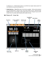
Страница 16: ...ble to be set within the SYSTEM tab M4 2 TimeLock Home Tab Frequency Displays the tuned frequency in a large bold font Read Only Tuning and Band selection Left and Right Arrows are used to navigate the spectrum AM and FM tuning spectrum Holding an arrow for longer than 2 seconds will increase the speed by a factor of 2 AM FM Band selector displays the band that the unit is tuned to Selecting the A...

Страница 17: ...lls the Station Long and Short Name Program Type Song Artist Album Genre Comments field RBDS scrolls the PI Call Letters PS Program Service PTY Program Type and RT Radio Text Any active alarm condition will override this data M4 2 TimeLock Home Tab Tuning and Band selection Frequency Multicast Album Art when available Station Logo when available Signal Noise Ratio Alarm Status Mode Selector AM FM ...

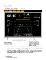
Страница 18: ...nd TimeLock correlation Integer values are displayed in Samples and Msec Positive indicates Analog is leading HD 1 negative lags Green indicates Correlation above 70 and Red below Calculates the Analog in samples as leading or lagging HD 1 Digital Slide bar displaying Analog moving against fixed HD 1 in real time Green indicates better than 70 correlation Slide bar displaying the TimeLock scale in...

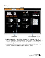
Страница 19: ...ditions are set with pull down windows Sliding the switch to the left side will ENABLE the alarm with the set conditions Orange switch indicates the alarm is enabled Relay Outputs are available for each alarm to be set to a specific relay output A pin out of the GPIO DB 15 is available on page 11 of this user manual Alarm Settings Alarm relay outputs via GPIO Figure 15 ...

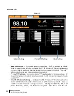
Страница 20: ...Private FTP Settings An optional private FTP may be setup for firmware updates By default this feature is disabled Slide the switch to the left indicated in orange to Enable private FTP Email Notifications Settings configures the M4 2 TimeLock for email alerts when Alarm conditions become active This feature is set to disable by default Slide the switch to the left indicated in orange to enable En...

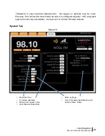
Страница 21: ... Test will send a test email to be sure it is configured properly SSL encrypted logins are currently unavailable coming soon in a future firmware release System Tab Network Time Firmware Updates Reset unit power cycle User Manual Download Misc settings Unit Firmware identification and build number date Figure 17 ...

Страница 22: ...ec M4 2 TimeLock is set to 75µsec by default Region US Euro Adjusts tune spacing between 100 KHz Euro and 200 KHz US default Alarms Lock Tuning Disables all tuning when any one alarm is enabled Digital Auto Force disables the tuner from falling back to Analog when and if the Digital signal drops below the threshold The tuner will mute in place of Analog About Read Only o Box ID M4 2 TimeLock o Ser...

Страница 23: ...p the M4 2 TimeLock from downloading the update directly from DaySequerra Please notify DaySequerra so future firmware updates are sent directly to the user Restore Factory Settings To restore your M4 2 TimeLock unit back to the original factory settings hold the UP arrow button in while power cycling the unit Release the UP arrow button once the power is restored to the unit The original factory ...

Страница 24: ...hall be void in the event a covered product has been damaged or failure is caused by or attributable to acts of God abuse accident misuse improper or abnormal usage failure to follow instructions improper installation or maintenance alteration or lightning power fluctuations and other incidental or environmental conditions Further product malfunction or deterioration due to normal wear is not cove...

Отзывы: